
0024
TM 10-4930-369-13&P
Figure 19. Pump Motor Electrical Enclosure.
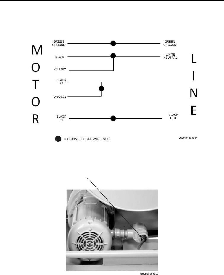
Figure 20. Pump Motor Wiring Diagram.
4.
Neatly arrange the wires (Figure 19, Item 5) in pump motor electrical enclosure (Figure19, Item 2).
5.
Replace the end cap (Figure 19, Item 3) on pump motor electrical enclosure (Figure19, Item 2).
6.
Tighten gland nut on (Figure 21, Item 1) on pump motor electrical enclosure.
Figure 21. Gland Nut on Pump Enclosure.
7.
At opposite end of the cable, insert wire-ends of the cable (Figure 22, Item 4) through the gland on bottom
of switch enclosure (Figure 22, Item 1). Feed cable through the gland until the outer jacket is visible within
enclosure.
002412