
TM 10-4930-369-13&P
FIELD MAINTENANCE
REPLACE FUEL NOZZLE HOUSING LOCKING PLATE
INITIAL SETUP:
Tools and Special Tools
Spill Kit (WP 0062, Item 20)
GMTK (WP 0063, Item 7)
Personnel Required
Quartermaster and Chemical Equipment
Materials/Parts
Repairer 91J
Apron, Rubber (WP 0062, Item 1)
Extinguisher, Fire (WP 0061)
References
Gloves, Chemical/Oil Protective (WP 0062, Item 10)
Goggles, Industrial (WP 0062, Item 13)
Equipment Condition
Pan, Drain, 5 gal cap (WP 0063, Item 6)
Rag, Wiping (WP 0062, Item 18)
FDS disconnected from power source (WP 0005)
REPLACE
WARNING
Personnel Protective Equipment (PPE), must be worn during maintenance and cleaning
procedures. Failure to comply may result in injury to personnel.
Chemical/Oil protective gloves and a rubber apron must be worn by personnel handling fuel.
Failure to comply may result in injury to personnel.
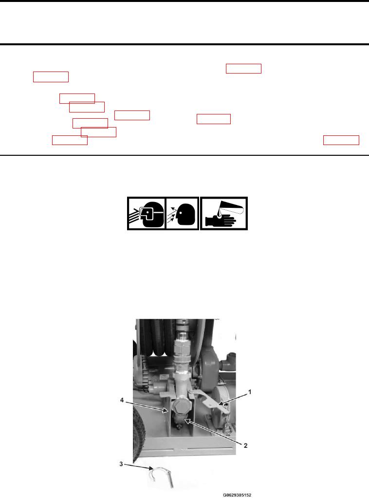
Remove Fuel Nozzle Housing Locking Plate
1. Remove the locking pin (Figure 1, Item 3) and swing out the locking plate (Figure 1, Item 1).
Figure 1.
Nozzle and Housing.
00251