 |
|||
|
|
|||
|
|
|||
| ||||||||||
|
|
 j. Remove the retaining ring (14) and slide the
tappets in the cylinder block. lf clearance is still
governor ball race (15), catching the fly balls (16)
excessive, the cylinder block is worn and must be
as they are released.
replaced.
g. Inspect the governor cross shaft for wear,
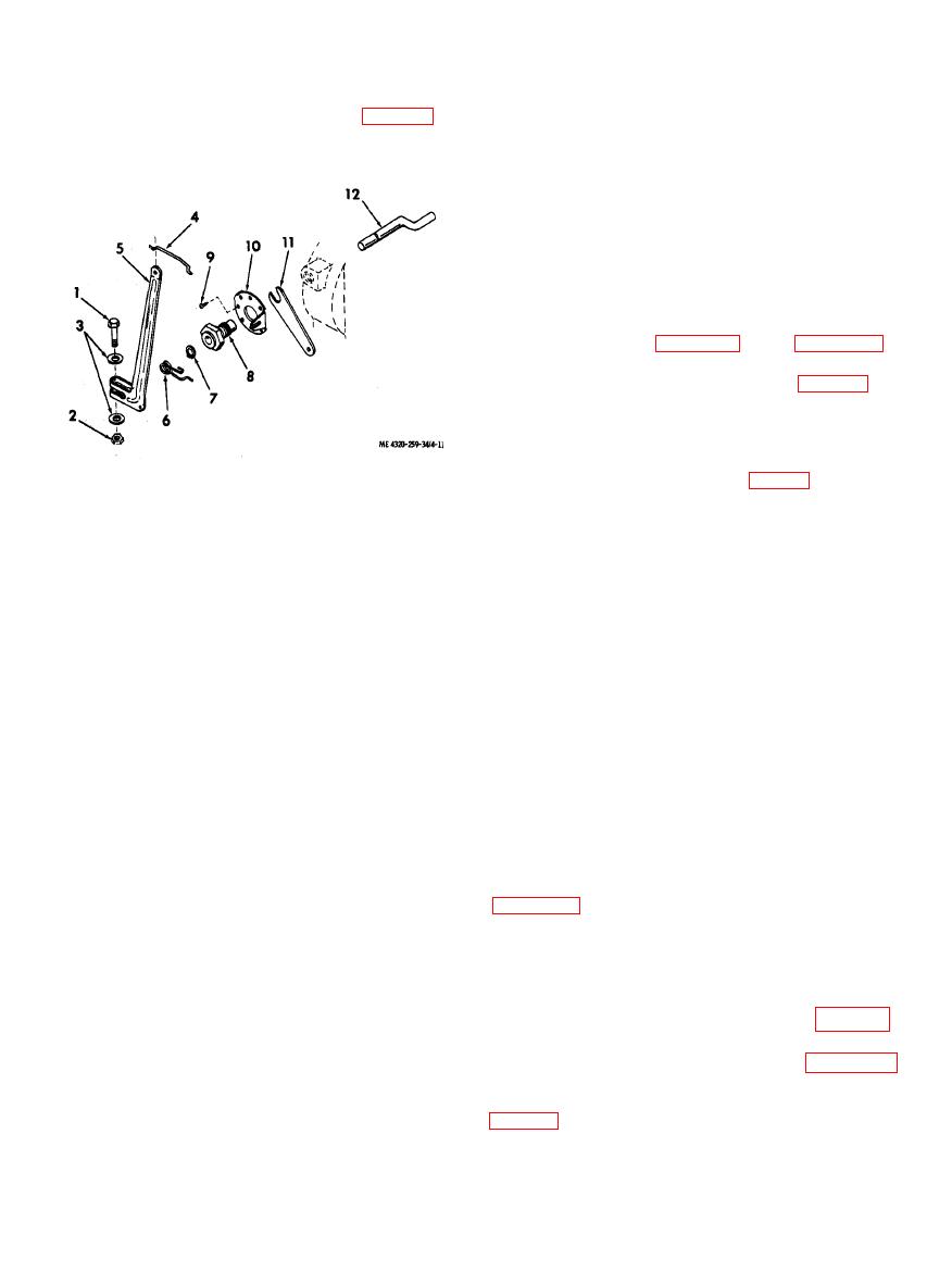
Slide the governor lever (5) and spring (6) from the
scoring, and distortion. Check the fit of the cross
outside end of the governor cross shaft (12).
shaft in the bushing. The shaft-to-bushing
clearance shall be 0.0012 to 0.0027 inch. If
clearance is excessive, replace the cross shaft, the
-
bushing,
or
both.
h. Inspect all other parts for cracks, distortion,
wear, damaged threads, and other damage; replace
damaged parts.
Reassemble the camshaft and governor as shown in
items 13 through 20 of figure 4-7 and in figure 4-
11. Note the following:
from the inside of the crankcase. Install the speed
control bracket (11), regulating disk (10), and
bushing (8) on the outside of the crankcase. Secure
the cross shaft with the retaining ring (7).
1. Clamping screw
7.
Retaining ring
2.
Nut
Bushing
8.
flyball retainer (18) on the camshaft (19) and
3.
Flat washer
Drive screw
9.
position the governor ball race (15) on the
10.
Regulating disk
4.
Throttle link
cam shaft. Secure the parts with the retaining ring
11.
5.
Governor lever
Speed control bracket
12.
Cross shaft
6.
Torsion spring
(14).
c. Insert the tappets (20) in the cylinder block.
Position the assembled camshaft and governor
assembly in the cylinder block and insert the
l. Remove the retaining ring (7). Unscrew the
cam shaft pin (13) from the bearing plate side of the
governor bushing (8) and remove the bushing,
cylinder block. Tap it into place so that the ends are
regulating disk (10), and speed control bracket
flush with the sides of the cylinder block.
(11). Remove the governor cross shaft (12) from
Caution: Do not attempt to insert the
the inside of the cylinder block.
camshaft pin from the power takeoff side of the
cylinder block. The camshaft pin hole on this
side is smaller in diameter and driving the pin
a. Clean all parts with an approved cleaning
through it may damage the cylinder block.
solvent; dry thoroughly.
d. Check the camshaft end play with a feeler
b. Inspect the camshaft for chipped or broken
gage inserted between the camshaft and block. End
gear teeth, scored or worn cams, and worn or scored
play shall be 0.005 to 0.020 inch. If end play is
bore. Insert the camshaft pin into the camshaft and
excessive, add shim washers at the breaker cam end
check the clearance. Camshaft pin-to-camshaft
of the camshaft.
c l e a r a n c e shall be 0.0010 to 0.0025 inch. If
e. Install the crankshaft and main bearings
clearance is excessive, replace the camshaft. If the
(para 4-14). Make sure timing marks on the
camshaft pin is ridged, grooved, or worn, also
crankshaft and camshaft are properly alined. After
replace the camshaft pin.
installing the crankshaft, check that the crankshaft
c. Inspect the governor ball race for scoring or
and camshaft rotate freely without binding.
distortion; replace a damaged race.
f. Install the magneto and flywheel (TM 5-4320-
d. Check the governor flyballs for wear, scoring,
259-12).
out-of-round condition, pits, and other damage;
replace damaged fly balls.
10).
e. Inspect the flyball retainer for cracks,
distortion, and wear; replace if damaged.
6).
f. Inspect the valve tappets for wear and scoring.
i. Install the centrifugal pump on the engine
Check the fit of the valve tappets in the bores of the
cylinder block. Valve tappet clearance in the
cylinder block shall be 0.0005 to 0.0020. If
clearance is excessive, check the fit of new valve
|
|
Privacy Statement - Press Release - Copyright Information. - Contact Us |