 |
|||
|
|
|||
|
Page Title:
Section IV. PISTON AND CONNECTING ROD |
|
||
| ||||||||||
|
|
 TM 5-4320-237-15
Section IV. PISTON AND CONNECTING ROD
95. General
The engine uses a conventional piston and
connecting rod assembly. The crankpin bear-
ing and wrist pin bearing are an integral part
of the connecting rod and are not removed
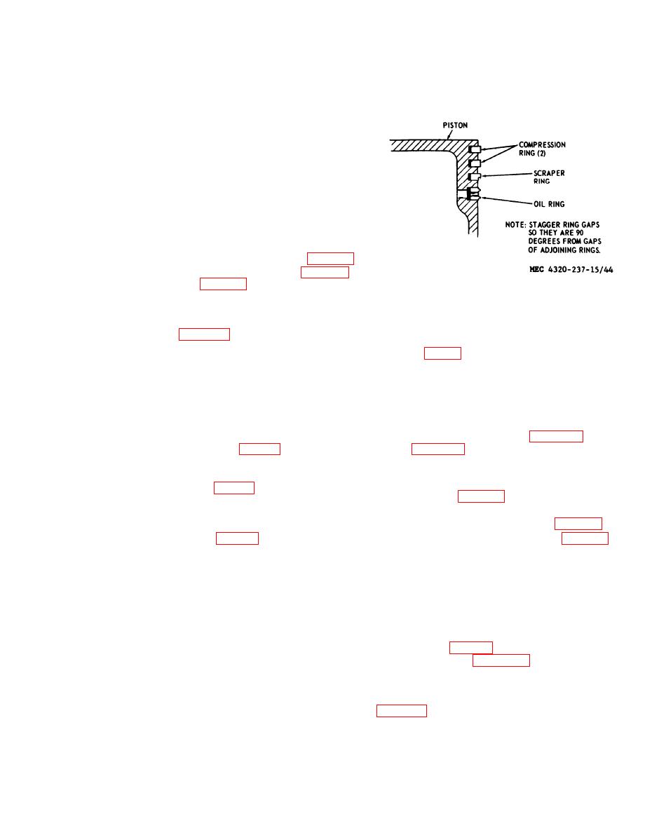
from the rod at disassembly. The piston uses
four piston rings, two compression rings, one
scraper ring, and one oil ring.
a. Removal.
(1) Remove the cylinder head (para 65).
(2) Remove the engine base (para 95).
(3) Refer to figure 42 to remove the as-
sembled piston and connecting rod.
b. Disassembly. Disassemble the piston and
connecting rod in the numerical sequence as
(5) Check the fit of the wrist pin in the
indicated in figure 43.
piston and connecting rod. Refer to
c. Cleaning and Inspection.
(1) Clean all parts with an approved clean-
(6) Inspect all other parts for cracks, dis-
ing solvent; dry thoroughly. Use the
tortion, and other damage; replace
sharpened end of a broken piston
damaged parts.
ring to scrape carbon deposits from
d. Reassembly. Reassemble the piston and
piston ring grooves.
(2) Inspect the piston for cracks, distor-
connecting rod in the reverse of the numeri-
tion, scoring, wear, and other dam-
cal sequence as illustrated in figure 43. Re-
fer to figure 44 for location of various piston
age. Refer to table 1 for tolerances.
rings.
(3) Inspect the connecting rod for cracks,
distortion, wear and other damage.
e. Installation.
Refer to table 1 for tolerances.
(1) Refer to figure 42 and install the as-
(4) Inspect piston rings for cracks, dis-
sembled connecting rod and piston.
tortion, and other damage. Check
(2) Install the engine base (para 94).
piston ring gap and side clearance.
Refer to table 1 for tolerances.
(3) Install the cylinder head (para 65).
Section V. CRANKSHAFT
97. General
98. Crankshaft
The crankshaft rides in tapered roller bear-
a. Removal.
ings in the crankcase. Bearing end play is
(1) Remove the piston and connecting
taken up by shims installed under the driven
rod (para 96).
end bearing plate. Cork seals prevent the oil
(2) Refer to figure 45 and remove the
from leaking around the rotating crankshaft.
crankshaft assembly.
Both ends of the crankshaft are threaded--
b. Disassembly. Disassemble the crankshaft
one end to receive the impeller of the pump
in the numerical sequence as illustrated in
and the other end to mount the starting rope
pulley.
c. Cleaning and Inspection.
|
|
Privacy Statement - Press Release - Copyright Information. - Contact Us |