 |
|||
|
|
|||
|
Page Title:
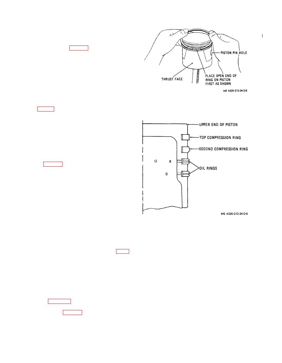
Figure 3-9. Piston ring placement. |
|
||
| ||||||||||
|
|
 (7) Inspect all other parts for cracks, distor-
tion, damaged threads, wear, and other damage;
replace damaged parts.
c. Reassembly and Installation.
(1) Use a feeler gage to check the piston fit in
the cylinder bore. Refer to table 3-1 for proper clear-
ance. The block and pistons must be at room tempera-
ture when piston fit is checked. You must measure the
clearance between the piston and cylinder at the center
of the piston skirt thrust faces. The thrust faces are 90
from the axis of the piston in hole. Check the fit of the
piston when it is approximately 2 inches down in the
cylinder bore in an inverted position. If the clearance
is too great, check the fit of a new standard size piston
in the cylinder bore.
(2) Check the clearance between the piston
pins (17, fig. 3-11) and sleeve bearings (19). Clearance
must be between 0.0002 an 0.0007 inch. If clearance is
not within this tolerance, press new sleeve bearings
into the connecting rods and ream and hone to provide
the proper clearance. After honing, 75 percent of the
sleeve bearing surface must contact the piston pin.
(3) If new pistons and piston pins are being
used, press a new sleeve bearing (19) into each con-
necting rod (15). Ream and hone the sleeve bearing to
provide proper clearance between bearing and piston
pin; refer to table 3-1.
(4) When pins, bushings, and pistons of the
proper size have been matched, assemble the pistons
to the connecting rods. The specified pin clearance
should permit a hand push fit in the piston at room
temperatures. Position a connecting rod in its piston.
Install the piston pin; secure with the new piston pin
retaining ring (16).
(5) To check the piston ring gap, slide the pis-
ton rings squarely into the cylinders in which they will
be used. You can insure squareness by pushing the
piston rings in th cylinder bore with an inverted pis-
ton. Remove the piston and check the ring gap with
feeler gage. If the ring gap is not at least 0.025 inch,
carefully file the rings to provide a larger gap.
(7) Assemble the remaining pistons, piston
(6) Install the bottom oil ring first by placing
pins, connecting rods, and piston rings.
the open end of the ring on piston, as shown in figure
(8) Lubricate the pistons, rings, rod bearings,
3-8. Spread ring only wide enough to slip over piston
and cylinder walls with engine oil before installing the
and into correct ring groove. You must take care not to
pistons. Stagger the piston ring gaps approximately
distort the ring. Install the remaining rings in the same
90 apart around the piston.
manner, working up from the bottom and installing
(9) Use a suitable ring compressor to compress
the top compression ring last. When you install the
the piston rings and install the assembled pistons and
compression ring that is second from the top, be sure
connecting rods in the same cylinders from which they
you install it on the piston with the scraper edge down,
were originally removed. The arrow on the top of the
piston must point in the direction of crankshaft rota-
otherwise oil pumping and excessive oil consumption
will result. See figure 3-9. Rings must be free to move
tion. Wrap the bottom end of the connecting rods with
in the groove. Check side clearance of each ring after
a cloth so that you do not damage the cylinder walls
you install it; refer to table 3-1 for clearances.
during installation.
|
|
Privacy Statement - Press Release - Copyright Information. - Contact Us |
