 |
|||
|
|
|||
|
Page Title:
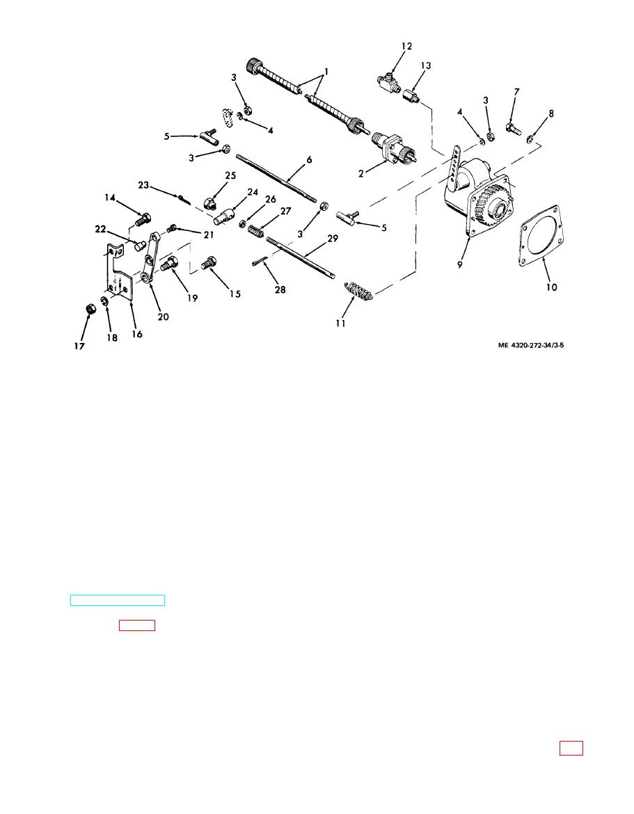
Figure 3-5. Governor and controls, exploded view, |
|
||
| ||||||||||
|
|
 16.
1. Flexible shaft
Bracket
17.
2. Drive adapter
Nut
18.
Lock washer
3. Nut
19.
4. Lock washer
Lever fulcrum pin
5. Ball joint
20.
Control lever
6. Control rod
21.
Screw
7. Screw
22.
Wire Connector
8. Lock washer
23.
Cotter pin
9. Governor
24.
Pin
10. Gasket
Lock nut
25.
11. Spring
26.
Retainer
12. Tee
27.
Spring
13. Adapter
28.
Cotter pin
14. Screw
29.
Adjusting screw
15. Screw
(2) Remove carburetor and manifolds. Refer
(7) Remove four screws (7) and lock washers
to TM 5-4320-272-12.
(8) securing governor assembly (9) to gear cover.
(3) Disconnect hourmeter-tachometer drive
(8) You can now withdraw the entire governor
adapter (2, fig. 3-5) from governor (9). Take care
assembly from the gear cover. Remove governor hous-
ing gasket (10).
that you do not kink or otherwise damage the flexible
(9) Disconnect speed control from governor
shaft (1).
(4) Unhook governor spring (11) from the gov-
control by loosening wire connector screw (21); with-
ernor lever and adjusting screw (29).
draw speed control wire from connector (22).
(10) Remove the governor control assembly by
(5) Disconnect the governor control rod link-
removing screws (14 and 15) securing it to the cylinder
age from the carburetor throttle lever by removing
nuts (3) and lock washers (4).
block and heat deflector.
(6) Disassemble the control rod linkage by
b. Governor Control Disassembly.
(1) After you have removed governor control,
removing ball joints (5) and nuts (3) from the control
rod (6).
disassemble by removing lever fulcrum pin (19, fig.
3-9
|
|
Privacy Statement - Press Release - Copyright Information. - Contact Us |