 |
|||
|
|
|||
|
Page Title:
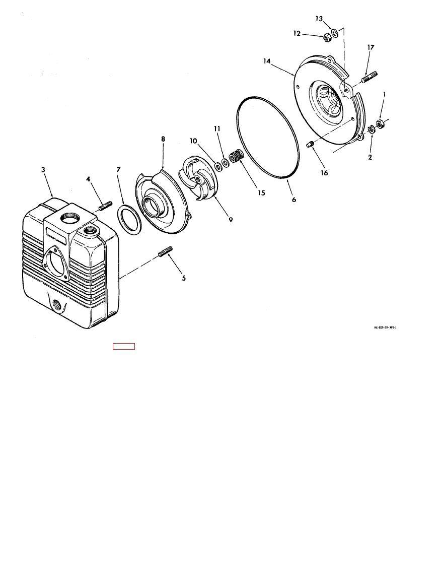
Figure 3-1. Centrifugal pump, exploded view. |
|
||
| ||||||||||
|
|
 KEY to fig. 3-1:
1. Nut
10.
Shim
2. Lock washer
11.
Shim
3. Pump body
12.
Nut
4. Stud
13.
Lock washer
5. Stud
14.
Seal plate
6. Gasket
15.
Shaft seal assembly
7. Volute gasket
16.
Volute pin
8. Volute
17.
Stud
9. Impeller
terclockwise and break it loose from the shaft. Turn
Do not remove the studs (4 and 5) unless they
d.
it from the shaft. Remove and save the shims (10
are damaged and require replacement.
and 11).
e. Two volute pins (16) position the volute (8)
g. Remove the four nuts (1.2) and lock washers
on the seal plate (14). Pull straight out on the
volute to remove it from the seal plate.
(13) that secure the seal plate (14) to the studs (17)
on the engine; remove the seal plate and shaft seal
f. A right-hand thread secures the impeller (9) to
the engine crankshaft. Place a block of wood on one
assembly (15).
of the impeller vanes and strike the block of wood
h. Remove the shaft seal assembly from the seal
with a hammer to rotate the impeller coun-
plate.
|
|
Privacy Statement - Press Release - Copyright Information. - Contact Us |