 |
|||
|
|
|||
|
|
|||
| ||||||||||
|
|
 TM 5-4320-258-34
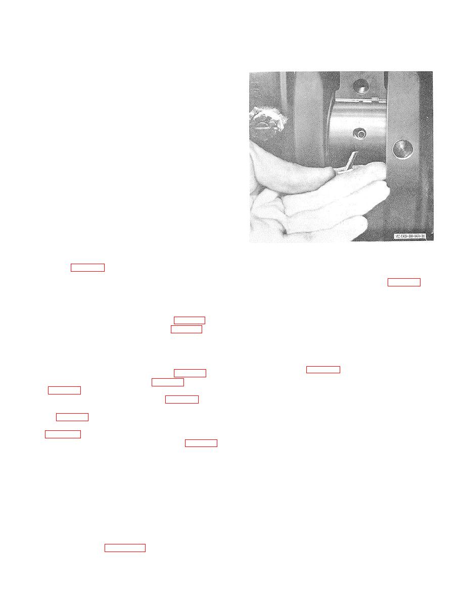
Rotate the crankshaft and roll the bearing shell from the
(10) Check the crank pin bearing journal-
cylinder block.
to-connecting rod bearing clearance with plastigage.
Lay a piece of plastigage material on the crankshaft
journal and install the connecting rod bearing cap.
Torque the nuts to 35 to 40 foot-pounds. Remove the
bearing cap and compare the width of the flattened
plastigage material with the scale markings on the
plastigage package to determine the clearance. The
bearing-to-journal clearance shall be 0.0006 to 0.0022
inch. If clearance is beyond these limits, replace the
bearing and/or the crankshaft as required.
(11) As an alternate method of checking
crank pin bearing journal-to-connecting rod bearing
clearance, install a 1/2-inch piece of 0.0022-inch-thick
feeler stock between the bearing and journal, and install
the bearing cap. Tighten the connecting rod cap bolts to
35 to 40 foot-pounds torque. Rotate the crankshaft to
detect drag. If clearance is within tolerance, a definite
drag will be felt. Disassemble the rod cap and remove
the shim stock. If clearance is not within tolerance,
replace the connecting rod bearings and recheck the
clearance. If clearance is still not within tolerance,
replace the crankshaft.
(12) Lubricate the crank pin bearing
Figure 4-16. Removing upper bearing shell with angular
journals and the sleeve bearings with engine oil. Install
pin.
the cap (13, fig. 4-14) on its connecting rod (20) and
crank pin bearing journal; secure with the two bolts (12)
(7) Pull the oil thrower (21, fig. 4-14) and
and nuts (11). Tighten the nuts to 35 to 40 foot-pounds
gear (22) from the crankshaft (40). Remove the key
torque. Install the cotter pins (10).
(23) and remove the thrust plate (24).
(13) Secure the remaining connecting rods
b. Cleaning and Inspection.
to !the crank pin bearing journals.
(1) Clean all parts with cleaning solvent
(14) Install the engine oil pan (para 4-6c).
(FED. Spec. P-D-680). Clean oil passages in the
(15) Install the cylinder head (para 4-3 c).
crankshaft with a rifle cleaning brush. Make sure all
4-11. Main Bearings and Crankshaft.
passages are open.
a. Removal and Disassembly.
With the
(2) Inspect the crankshaft for cracks, worn
engine mounted on an engine overhaul stand, proceed
or scored journals, damaged threads, and burred
as follows:
keyways. Refer to table 4-1 for wear limits. If magnetic
(1) Remove the cylinder head (para 4-3 a).
particle inspection equipment is available, use it to
(2) Remove the oil pan (para 4-6 a) and oil
check the crankshaft for hidden flaws. Replace a
pump (para 4-7 a).
damaged crankshaft.
(3) Remove the gear cover (para 4-8a).
(3) Inspect the gear for cracked, chipped
(4) Remove the flywheel and flywheel
and broken teeth; replace a damaged gear.
housing (para 4-9 a).
(4) Inspect the bearing shells for cracks
(5) Remove the pistons and connecting
and scoring. New bearings are smooth and highly
rods (para 4-10 a).
polished. After a few hours of operation, the bearing
(6) Remove the bolts (26 and 30, fig. 4-14)
surfaces become leaden grey in color and develop
and flat washers (31 ) that secure the main bearing caps
minute craters which give the bearing surfaces an
(27, 32, 34, and 37) to the cylinder block. Loosen the
almost cellular appearance.
This is a natural
bearing caps by tapping them with a plastic hammer.
characteristic of the bearing and does not indicate
Remove the bearing caps and lower bearings (29, 33,
bearing failure. Replace bearings if they are scored or
36, and 39).
damaged. Check the bearing thickness with a ball
micrometer. Check several locations on the bearing. If
Note: Upper main bearing shells can be
thickness is less than 0.920 inch, replace the bearing.
removed without removing the crankshaft. To remove
(5) Inspect the bearing caps for cracks and
the upper shell, remove the main bearing cap at the
distortion and for burrs and gouges of the seating
defective bearing and remove the lower bearing shell.
surfaces. Clean up any burrs with a fine stone to assure
Insert a pin with an angular head in the oil hole of the
proper seating of the bearing cap on the block.
crankshaft as shown in figure 4-16.
4-22
|
|
Privacy Statement - Press Release - Copyright Information. - Contact Us |