 |
|||
|
|
|||
|
Page Title:
Installation or Setting up Instructions |
|
||
| ||||||||||
|
|
 TM 10-4320-202-15
open area. The exhaust gases contain carbon
2-7. Installation or Setting up
monoxide, a poisonous, odorless, and invisible
Instructions
deadly gas.
a. Location. Position the pumping assembly
on a firm, moderately level area as close as
c. Indoor Installation. Follow the same pro-
conveniently possible to the fuel supply. Choose
cedure used for outdoor installation, but vent
an area which will provide easy access for
the exhaust fumes outdoors by removing the
servicing vehicles.
muffler and it's associated piping. Then con-
nect 1 inch npt piping to the exhaust port of
Warning: Be sure the unit is properly
the engine to vent exhaust fumes out of doors.
grounded before operation.
Be sure ventilation is adequate for proper
engine cooling and to support combustion.
Warning: Do not operate the engine in a
Connect the ground cable to a low-resistance
ground connection.
closed area unless the exhaust is vented to an
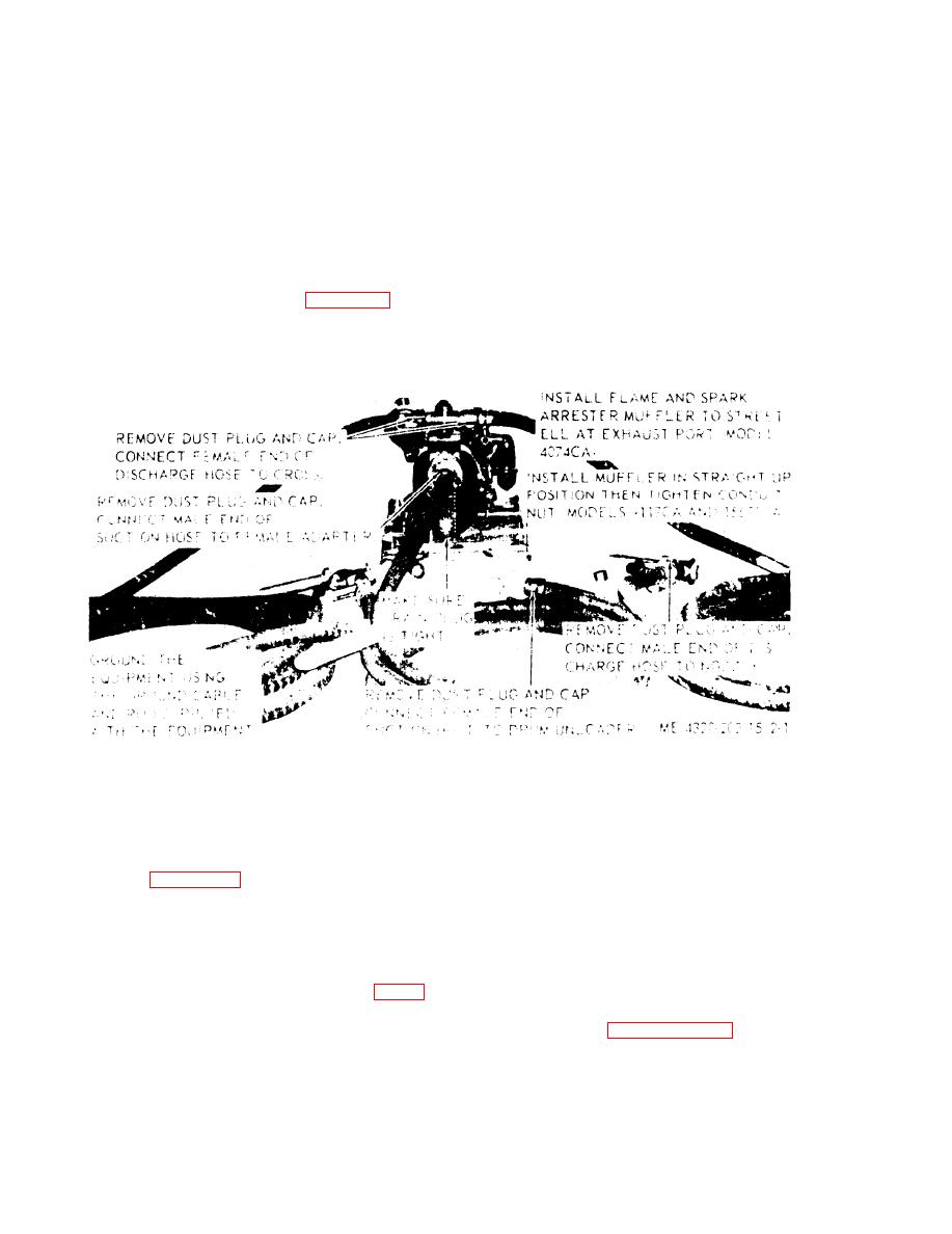
Figure 2-1. Pump installation and setup.
Section Il. MOVEMENT TO A NEW WORKSITE
e. Attach a red danger shipping tag indicat-
2-8. Dismantling for Movement
ing combustible or flammable equipment.
a. Reverse the installation procedures illus-
trated in figure 21. Thoroughly drain all
2-9. Reinstallation and Setup after
hoses. Install dust plugs and caps on hoses
Movement
and fittings.
b. Remove drain plug from the bottom of
Warning: No smoking or open fire within
the pump. Allow fluid to drain from pump
50 ft. of equipment. Combustible vapors may
body. Reinstall the plug.
be present in the hoses and pumping body.
11.
Reinstallation of the pumping assembly after
d. Secure tip covers (Models 9117CA and
movement, refer to paragraphs 21 through
15671 CA) and side panels (Model 4074CA).
2-7 .
2-2
|
|
Privacy Statement - Press Release - Copyright Information. - Contact Us |
