 |
|||
|
|
|||
|
Page Title:
Engine Block and Cylinder Sleeve |
|
||
| ||||||||||
|
|
 (13) Install the connecting rod bearings in the
connecting rods, and connecting rod caps. Pull the
connecting rods against the crank pins. Install the
connecting rod caps on the connecting rods; secure with
two capscrews. Tighten the capscrews to 57-59 ft-lbs of
(14) Assemble the remaining engine parts and
accessories in reverse order of disassembly.
6-19. Engine Block and Cylinder Sleeve
a. General. The engine block is the most
important and largest engine component. Every other
engine component is attached, or function is related,
directly to the engine block. The engine block is
equipped with cylinder sleeves.
b. Removal.
MEC 4320-240-15/6-26
(1) Refer to paragraph 6-11b and remove the
manifold.
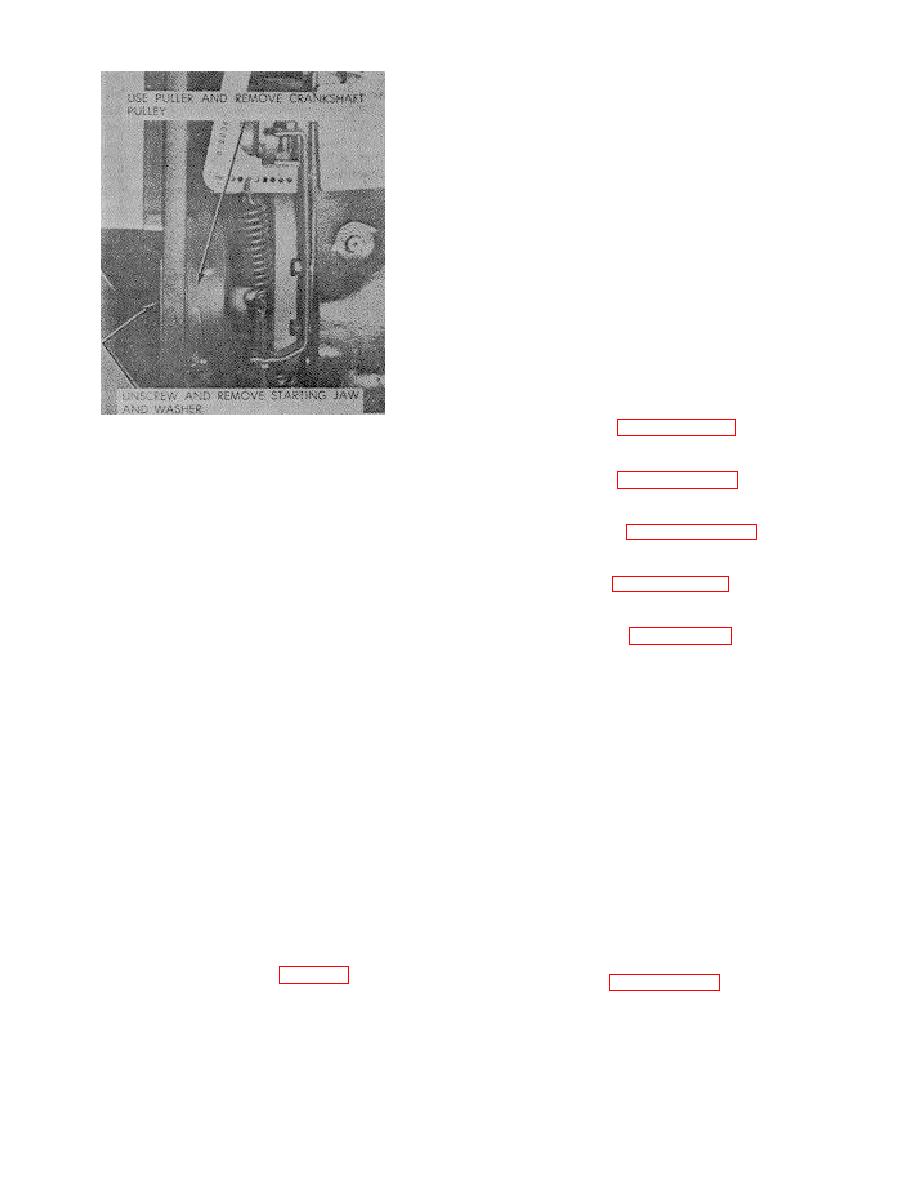
Figure 6-26. Dampener and pulley
removal and installation.
(2) Refer to paragraph 6-12b and remove the
cylinder head.
(d) Try to turn the crankshaft by hand. If the
crankshaft will not turn or a definite drag is felt, bearing-
(3)
Refer to paragraph 6-18b and remove
to-bearing journal -clearance is within tolerance.
crankshaft and camshaft.
(7) After all main bearings have been installed,
(4) Refer to paragraph 3-50b and remove water
check crankshaft end play using a dial indicator. If end
pump.
play is not between 0.003 and 0.007 inch, replace the
front sleeve bearing.
(5)
Refer to figure 3-20 and remove the
(8) If the camshaft gear has to be replaced.
Removal of the gear from the camshaft requires an
(6)
Make sure all engine accessories and
arbor press and a suitable support plate to hold the gear.
components are removed, refer to chapter 6 section I
Do not attempt to remove the gear by makeshift
and chapter 6 section II and remove all components and
methods that may distort the shaft or gear.
accessories.
(9) Install the camshaft bearing journals and
(7) Remove cylinder sleeves, using sleeve puller.
camshaft bearings with feeler stock cut in strips inch
wide. Dress the feeler stock with a stone to eliminate
c. Cleaning and inspection.
burs or feathered edges.
Clearance between the
bearings and journals must be between 0.0015 and
(1) Remove dirt and grease deposits from the
0.003 inch.
block with a putty knife. Steam-clean the block.
(10) If clearance exceeds 0.003 inch, remove the
(2) Inspect the block for cracks, damaged sealing
camshaft from the block and install new camshaft
surfaces, scored or damaged bearing sets, damaged
bearings. The camshaft bearings are presized and do
threads, loose or damaged studs, corrosion in the water
not have to be honed after installation.
jacket, or other defects.
(11) Install the camshaft (fig. 6-30). Make sure
(3) Refer to paragraph 6-16d and check piston fit
the timing marks on the crankshaft gear and camshaft
in cylinder sleeve.
gear line up.
(4) Check cylinder sleeve wear with an inside
(12) Check the crankshaft and camshaft gears for
micrometer. Measure the cylinder bore
backlash. The backlash must be .002 - .004.
6-24
|
|
Privacy Statement - Press Release - Copyright Information. - Contact Us |
