 |
|||
|
|
|||
|
Page Title:
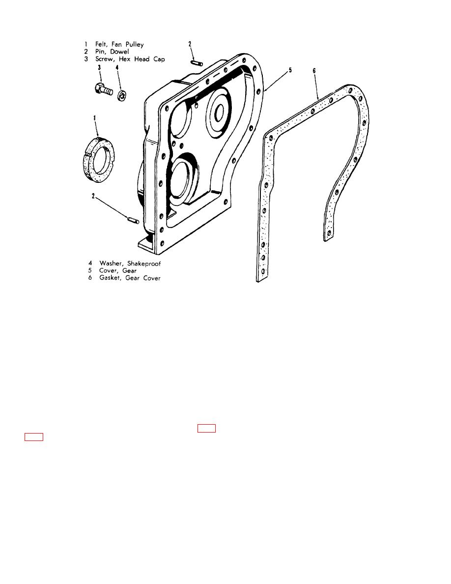
Figure 6-27. Gear cover removal and installation. |
|
||
| ||||||||||
|
|
 MEC 4320-240-15/6-27
Figure 6-27. Gear cover removal and installation.
at 45 degree intervals below the travel of the lowest
(a) Clean and well lubricate the seal ring seating
piston ring where the cylinder is not worn. Compare this
surfaces with liquid soap. Do not use oil on rubber
measurement with a measurement taken about inch
rings.
below the top of the cylinder. The maximum allowable
cylinder wear (the difference between these two
(b) Slip the seal rings over the sleeve and into the
measurements) is 0.008 inch.
grooves. Refer to figure 6-32 and run a pencil or like
instrument around finder the ring to distribute the rubber
(5) Replace the block if it is cracked or defects
material around the sleeve more evenly.
cannot be repaired. Replace loose or damaged studs.
Retap damaged threads.
(c) Soap the seal rings and surrounding areas.
(6) If a proper piston fit cannot be attained (para
Aline the sleeve in the crankcase and force it in with a
firm thrust of the hands. Heavy hammering or driving is
unnecessary and undesirable.
cylinder sleeves wear exceeds 0.008 inch, rebore and fit
with new pistons, or replace the cylinder sleeves.
(2) Refer to figure 6-33 and check the sleeve
bores for distortion that might have occurred due to
d. Installation.
inaccurate placement of the seal ring material.
(1) Install the cylinder sleeves as follows:
6-25
|
|
Privacy Statement - Press Release - Copyright Information. - Contact Us |
