 |
|||
|
|
|||
|
|
|||
| ||||||||||
|
|
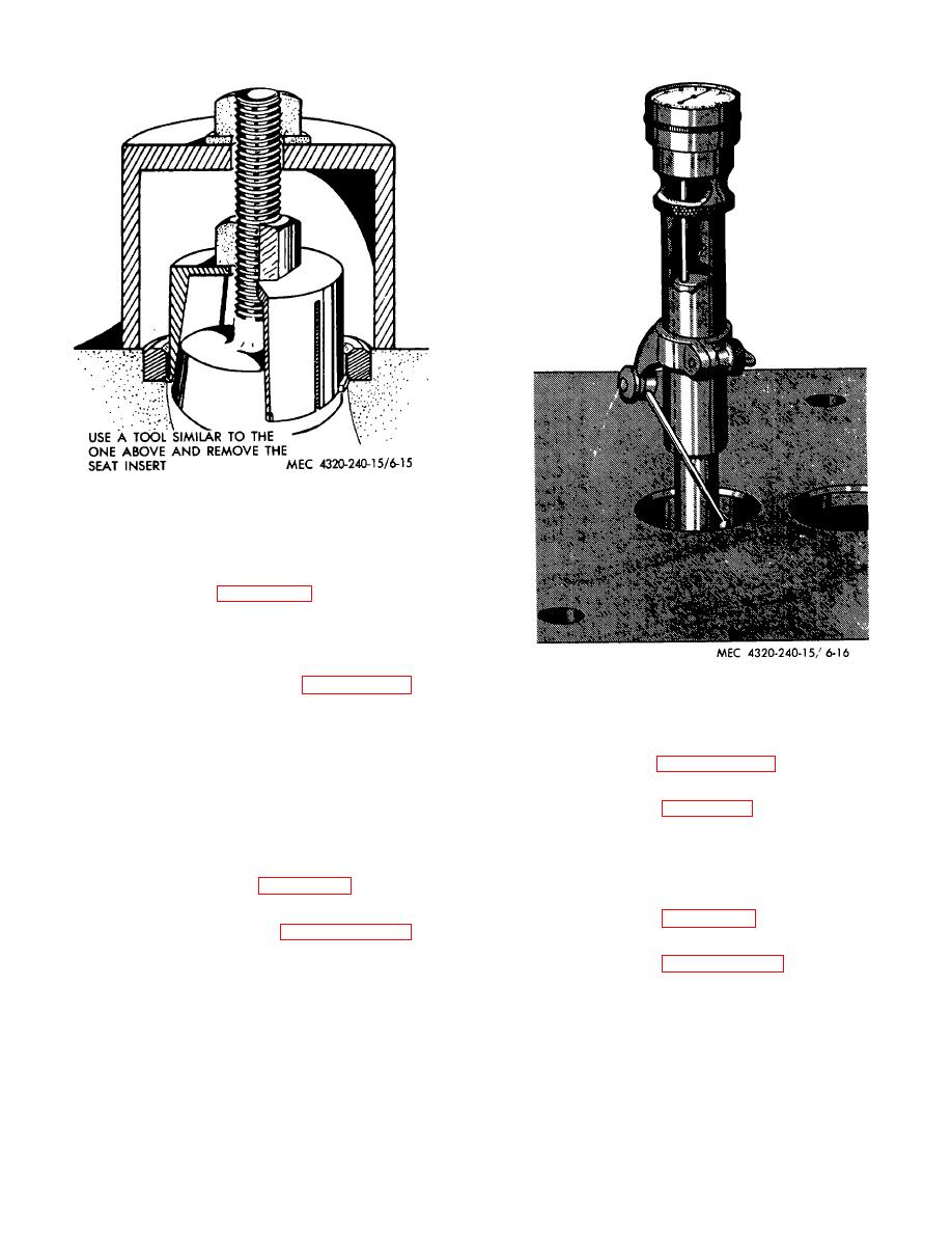 Figure 6-15. Seat insert removal.
(2) Position engine on side, be careful not to
damage any of the protective housing.
(3) Refer to figure 6-17, remove nuts (9),
washers (7), capscrews (8), and special capscrews (3).
(4) Remove oil pan and gasket.
Figure 6-16. Indicating valve seat trueness.
c. Disassembly.
Refer
to
and
disassemble oil pan.
b. Removal.
d. Cleaning, Inspection, and Repair.
(1) Refer to paragraph 6-14b and remove the
(1) Wash oil pan in an approved cleaning
oil pan.
solvent, and dry thoroughly.
(2) Refer to figure 6-18 and remove the oil
(2) Inspect for cracks, dents, and missing
pump.
parts.
c. Installation.
the oil pan.
(1) Refer to figure 6-18 and install the oil
pump.
install oil pan on engine and engine in pumping unit in
(2) Refer to paragraph 6-14b and install oil
reverse order of removal.
pan on engine and engine in pumping unit in reverse
order of removal.
6-15. Oil Pump
6-16. Pistons and Connecting Rods
a. General. The oil pump is located at the lower end of
the cylinder block, and is covered by the oil pan. The
sole purpose of the oil pump is to circulate oil under
pressure to all moving parts of the engine.
positioned in the cylinder bores. Their
6-15
|
|
Privacy Statement - Press Release - Copyright Information. - Contact Us |
