 |
|||
|
|
|||
|
|
|||
| ||||||||||
|
|
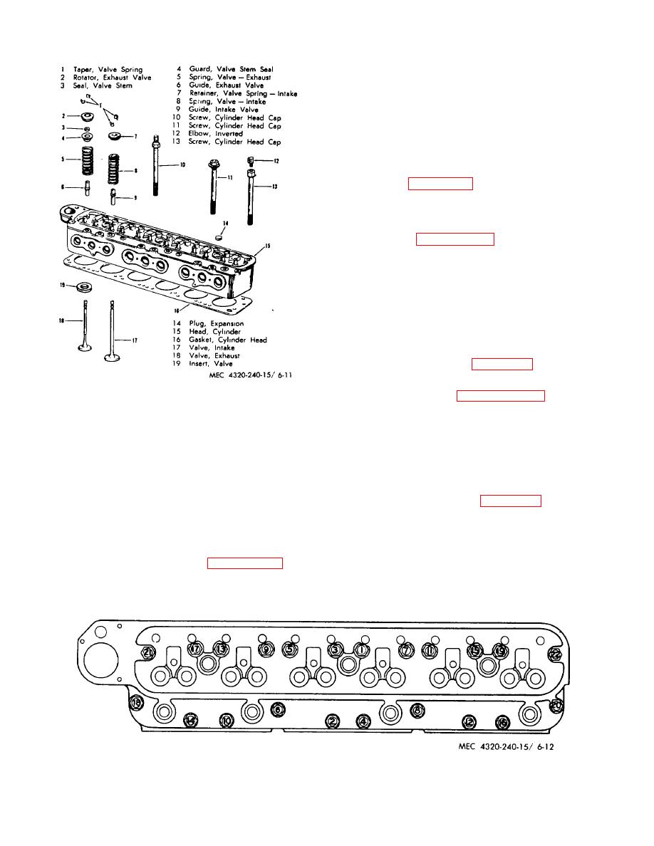 (1) Position cylinder head on cylinder block
using a new cylinder head gasket. A small amount of
cement may be used around water and oil holes of the
cylinder head ,i U' to provide a tight seal at those points.
Never install cylinder head without closing spark plug
holes. This is important because small washers or nuts
may find their way into the combustion chamber and
cause serious damage. Secure the cylinder head with
the cylinder head hold down capscrews. Tighten the
capscrews a little at a time and in the sequence
indicated in figure 6-12 continue tightening in that
rotation until all cylinder head capscrews are tightened
to 98 to 100 ft-lbs torque.
(2) Complete cylinder installation in reverse
order noted in paragraph 6-12b.
6-13. Valves, Seats, and Guides
a. General. The valves are positioned in the
cylinder head. They are operated by the cam shaft and
are so timed as to let in a mixture of gasoline and air at
just the right instant. They also serve in exhausting the
burned gas.
(1) Refer to paragraph 6-12b and remove
Figure 6-11. Cylinder head-exploded view.
cylinder head.
(2) The end of each valve stem is fitted with
a shallow steel retainer that accommodates the end of
(3) Inspect the cylinder head for cracks,
the valve spring, and is held to the stem by a pair of
breaks, and warpage. Check the flatness of the cylinder
split tapers. The locking tapers must be removed before
head with a straight edge and feeler gage in three
the valve can be withdrawn. To release the lock from
positions lengthwise and five positions crosswise. The
the recess in the spring retainer, it is necessary to use a
maximum permissible warpage is 0.004 inch low in the
spring compressor, refer to figure 6-13 and press down
center lengthwise, gradually decreasing toward the
until the tapers fall free.
ends, or 0.003 inch crosswise in localized low spots.
Replace a cracked, broken, or warped cylinder head.
(3) Lift each valve from the cylinder head.
Place them in order in a rack to assure that each will be
reassembled in the same valve guide from which it was
e. Reassembly.
Refer
to
and
removed.
reassemble cylinder head.
f. Installation.
Figure 6-12. Cylinder head tightening sequence.
6-12
|
|
Privacy Statement - Press Release - Copyright Information. - Contact Us |
