 |
|||
|
|
|||
|
|
|||
| ||||||||||
|
|
 (6) If it has been determined that valve guide
replacement is required, this operation should be done
at this time. Old guides may be removed with a suitable
puller or by reaming to a thin shell and collapsing them.
New guides are pressed in place on an arbor press with
the aid of a mandrel. Service guides are especially
machined to provide proper stem clearance without
further reaming after installation. In production, the
valve guide shoulders are intentionally held above the
cylinder head upper service to avoid valve binding
caused by cocking the guide if one side of the shoulder
contacts unevenly. Do not try to bottom these guides.
Install service guides in the same way. Use .010 inch
feeler stock as a spacer under the shoulder when
installing, (fig. 6-14).
(7) Check the exhaust valve seat inserts for
cracks or loose mounting. Refer to figure 6-15 and
remove any defective valve seats. Replace seats with
new 1/32 oversized valve seats. Counterbore the valve
seats to a diameter of 1.655 to 1.656 inches. This will
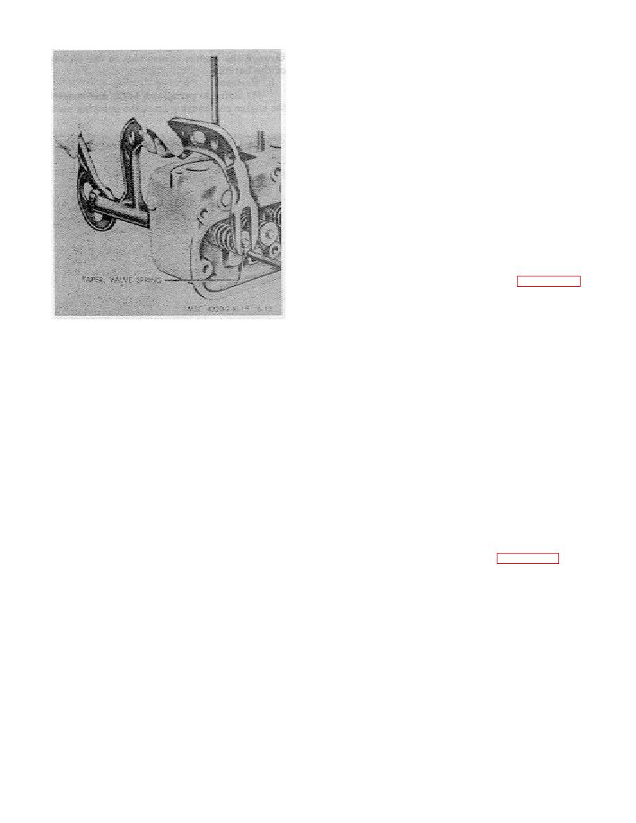
Figure 6-13. Removing valves.
provide a 0.003 to 0.005 inch press fit. Counterbore
deeply enough so that the boring tool will clean up the
bottom of the bore to assure proper heat conduction
(4) Do not remove the valve guides or seats
from the valve insert. Chill the valve seat in dry ice for
unless inspection indicates that they are faulty.
20 minutes. Install the valve seat in place with a piloted
driver using an arbor press or by applying light blows
c. Cleaning, Inspection, and Repair.
with a hammer until the valve seat is resting against the
bottom of the bore.
(1) Clean the valves, valve springs, retainers,
and valve stem caps with an approved cleaning solvent;
(8) Check the valve springs for cracks and
dry thoroughly. Remove carbon deposits with a wire
distortion. Test compression strength with a spring
brush.
tester. Compression strength must be as follows:
(2) Clean the valve guides installed in the
Valve closed-Spring length 1 15/16" Comp. Press 49
cylinder head with a valve guide cleaner or a wire brush.
lbs. 4 lbs.
Remove all lacquer and other deposits.
Valve open-Spring length 1 19/32" Comp. Press 86 lbs.
6 lbs.
(3) Clean valve seats with a wire brush.
(4) Inspect the valves for cracks, bent stems,
(9) Grind the valve seats. The seat angle is
distortion, and wear. If the valves are not seriously
45 degrees. Use a dial indicator figure 6-16 to check
damaged, regrind them. After grinding, the valve head
the valve seat for runout. The total indicator reading
thickness must be at least 50 percent of the thickness of
must not exceed 0.002 inch. Clean the valve seat and
a new valve. Replace the valves if they are ground to
surrounding area thoroughly after grinding.
less than this amount. Check the reground valves on V
blocks with an indicator. The contact face must be true
(10) After the valves and seats have been
with the stem to within 0.002 inch. Repeat the refining
refaced and reground coat the seat lightly with Prussion
operation if necessary.
blue and drop the valve into place, oscillating it slightly
to transfer the blue pattern
(5) Check for loose or worn valve guides.
Check the internal diameter of the valve guide with a
telescope gage and a micrometer. Replace guides that
are worn to a bellmouthed shape.
6-13
|
|
Privacy Statement - Press Release - Copyright Information. - Contact Us |
