 |
|||
|
|
|||
|
|
|||
| ||||||||||
|
|
 TM 5-4320-234-34
to 15 to 20 foot-pounds torque.
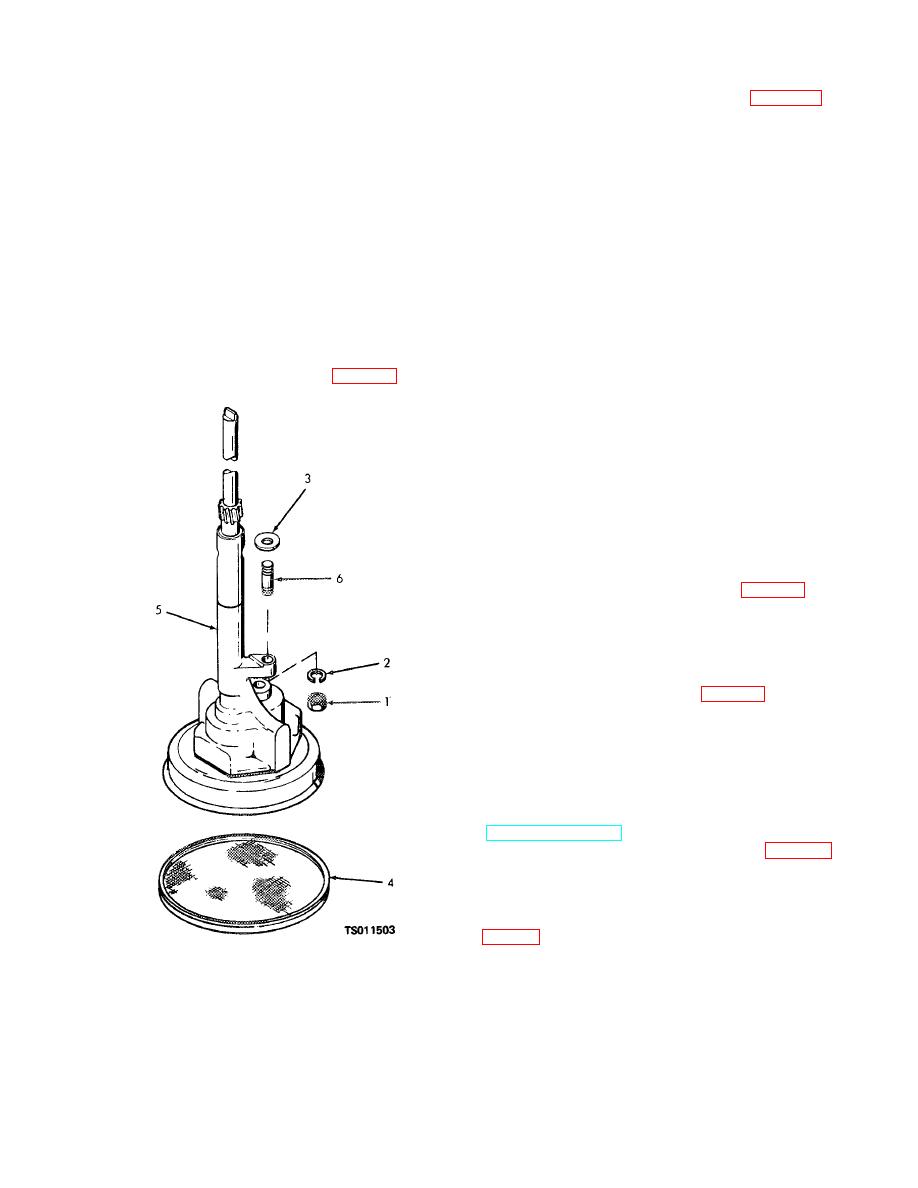
(2) Remove the nut (1, fig.
4-7) and
(5) Position the gaskets (7) on the oil pan (6).
lockwasher (2) securing the engine oil pump to the
Install the oil pan and gaskets on the engine block;
bearing cap. Remove the oil pump and flat washer (3).
secure with the 18 assembled washer screws (5).
(3) Remove the screen (4) from the bottom of
Tighten the screws to 12 to 16 foot-pounds torque.
the oil pump (5).
(6) Coat the male threads of the elbow (4)
b. Cleaning and Inspection.
with thread sealing compound and install the elbow in
the drain pan. Coat the male threads of the nipple (3)
WARNING
with thread sealing compound and install the nipple in
Clean all parts in a well-ventilated area.
the elbow. Install the coupling (2) on the nipple, and
Avoid inhalation of solvent fumes and
install the oil drain plug (1) in the coupling.
prolonged exposure of skin to cleaning
solvent. Wash exposed skin thoroughly.
4-6. Engine Oil Pump
Dry cleaning solvent (Fed. Spec. P-D-680)
used to clean parts is potentially dangerous
a. Removal.
to personnel and property. Do not use near
open flame or excessive heat. Flash point of
(1) Remove the engine oil pan (para 4-5).
solvent is 100 F. to 138 F. (38 C. to 59 C.)..
(1) Clean all parts with dry cleaning solvent
(Fed. Spec. P-D-680). Allow all parts to dry thoroughly
before reinstallation.
(2) Inspect the screen for holes, clogging, and
distortion. Replace a damaged screen.
(3) Check the fit of the drive shaft in the
pump body. There shall be no excessive play. Replace
the oil pump if the shaft is damaged, or if the play is
excessive.
c. Installation.
(1) Install the screen (4, fig. 4-7) on the
bottom of the oil pump (5).
(2) Position the washer (3) and oil pump (5)
on the main bearing so that the drive gear engages the
toothed portion of the camshaft. Secure the pump with
the nut (1) and lockwashers (2).
(3) Install the oil pan (para 4-5).
4-7. Gear Cover
a. Removal and assembly.
(1) Remove the governor from the engine
(para 34).
(2) Remove the water pump from the engine
(TM 5-4320-234-12, para 4-31).
(3) Remove the starting jaw (1, fig. 4-13) and
collar (2) that secure the pulley (3) to the front end of the
crankshaft; remove the pulley and key (4) from the
crankshaft.
(4) Remove the capscrews (1, 3, 6, and 10,
1. Nut
4. Screen
lockwashers (2, 9, and 12), and copper washers (4 and
2. Lockwasher
5. Engine oil pump
7) that secure the gear cover (14) to the engine block;
3. Flat washer
6. Stud
remove the gear cover and gear cover housing gasket
(15) from the front end plate (19).
Figure 4-7. Engine oil pump installation.
4-10
|
|
Privacy Statement - Press Release - Copyright Information. - Contact Us |
