|
| |
TM 9-2330-398-24
3-27.
ALTERNATOR REPAIR (continued).
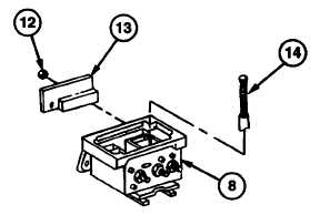
18. Install diode trio (13) on regulator housing (8) with
three nuts (12).
19. Install brush and spring assembly (14) in regulator
housing (8).
NOTE
Steps 20 through 24 cover installation of voltage regulator.
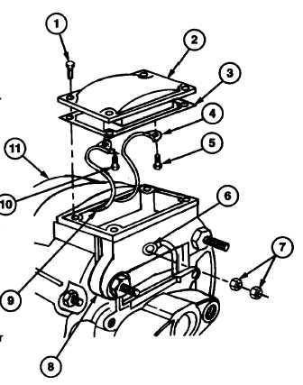
20. Install new gasket (3) over red lead (4), diode trio electrical lead (6), and black lead (9).
21. Install diode electrical lead (6) on regulator housing (8) with two nuts (7).
22. Install black lead (9) to left (negative) terminal of regulator (2) with screw (8).
23. Install red lead (4) to right (positive) terminal of regulator (2) with screw (5).
NOTE
Perform step 24 only if voltage regulator
does not require adjustment.
24. Secure regulator (2) to alternator (11) with four
screws (1).
d.
ADJUSTMENT
NOTE
•
Adjustment may be required during
prolonged operation in extremely low or
high temperatures to make sure batteries
are properly charged.
•
Be careful with gasket on regulator. If it is
damaged, regulator will have to be removed
to replace it.'
1.
If necessary, remove four screws (1), regulator (2),
and gasket (3) from alternator (11).
3-90
|