|
| |
TM 9-2330-398-24
3-27.
ALTERNATOR REPAIR (continued).
CAUTION
Do not overtighten screws on voltage adjustment strap. Voltage regulator will be damaged.
NOTE
Changing position of voltage adjustment strap will change output by 0.4 V dc.
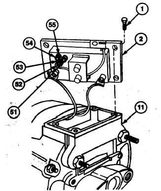
2.
Remove two screws (54) and voltage adjustment strap (53) from voltage adjustment posts A, B, or C, (52, 51 or 55) of
regulator (2).
3.
For output voltage of 14.4 V dc (HIGH setting), install voltage adjustment strap (53) on adjustment posts B and C (51
and 55) of regulator (2) with two screws (54).
4.
For output voltage of 14.0 V dc (MED setting), install voltage adjustment strap (53) on adjustment posts A and C (52
and 55) of regulator (2) with two screws (54).
5.
For output voltage of 13.6 V dc (LOW setting), install voltage adjustment strap (53) on adjustment posts B and A (51
and 52) of regulator (2) with two screws (54).
6.
Install regulator (2) and gasket (3) on alternator (11) with four screws (1).
FOLLOW-ON MAINTENANCE:
•
Install alternator (para 2-100).
3-91
|