|
| |
TM 9-2330-398-24
3-27. ALTERNATOR REPAIR (continued).
7.
Install insulating bushing (41) in each of two rectifier assemblies (32).
8.
Install two rectifier assemblies (32) in slip ring end housing (15) with two insulating washers (40), guard washers (39),
washers (38), and screws (37). Tighten screws (37) only enough to hold rectifier assemblies (32) in place.
9.
Install red lead (4) and black lead (9) on two rectifier assemblies (32) with two screws (33). Route red lead (4) and
black lead (9) through opening in slip ring end housing (15).
10. Install capacitor (44) and clamp (43) in slip ring end housing (15) with three screws (42).
NOTE
Red lead and black lead run through opening between slip ring end housing and regulator housing.
11. Install new gasket (30), regulator housing (8), and positive and negative output terminal bolts (35 and 34) on slip ring
housing (15).
12. Install two nuts (27), washers (28), and nuts (29), on positive and negative output terminal bolts (35 and 34).
13. Using tags as a guide, install six electrical leads of rectifier assemblies (32) and three electrical leads of stator (25) to
slip ring end housing (15) with three nuts (36).
NOTE
Make sure all electrical leads are not pinched between rectifier assemblies and slip ring end housing
before tightening screws.
14. Tighten two screws (37) on two rectifier assemblies (32).
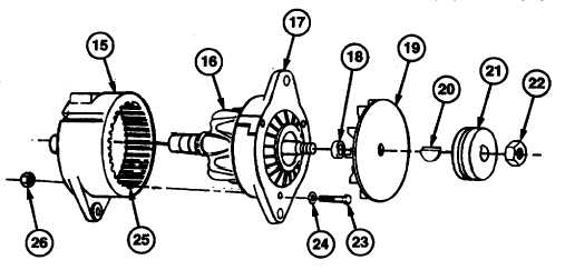
15. Install drive end housing (17) and rotor (16) on stator (25) and slip ring end housing (25) with three screws (23),
washers (24), and nuts (26).
16. Install spacer (18) and Woodruff key (20) on shaft of rotor (16).
17. Install fan holder assembly (19) and groove pulley (21) on shaft of rotor (16) with nut (22).
3-89
|