|
| |
TM 9-2330-398-24
3-27.
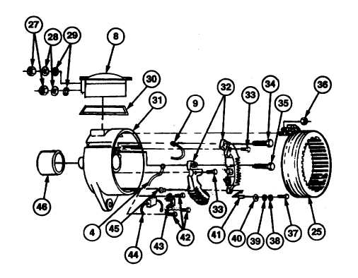
ALTERNATOR REPAIR (continued).
12. Remove three nuts (36) and three electrical leads of stator (25) and six electrical leads of rectifier assemblies (32)
from slip ring housing (15).
13. Remove two nuts (27), washers (28), and nuts (29) from negative and positive output terminal bolts (34 and 35).
14. Remove negative and positive output terminal bolts (34 and 35), regulator housing (8), and gasket (30) from slip ring
end housing (15). Discard gasket.
15. Remove three screws (42), clamp (43), and capacitor (44) from two rectifier assemblies (32).
16. Remove two screws (33), and red lead (4) and black lead (9) from two rectifier assemblies (32).
17. Remove two screws (37), washers (38), guard washers (39), insulating washers (40), and two rectifier assemblies (32)
from slip ring end housing (15).
18. Remove insulating bushing (41) from each of two rectifier assemblies (32).
19. Remove four terminal stud insulating bushings (45) from slip ring end housing (15).
20. Remove flanged dust cap (46) from slip ring end housing (15).
3-86
|