Order this information in Print

Order this information on CD-ROM

Download in PDF Format


Click here to make tpub.com your Home Page

Page Title: DISASSEMBLY
Back | Up | Next

Click here for a printable version

Google


Web
www.tpub.com

Home


Information Categories
.... Administration
Advancement
Aerographer
Automotive
Aviation
Combat
Construction
Diving
Draftsman
Engineering
Electronics
Food and Cooking
Math
Medical
Music
Nuclear Fundamentals
Photography
Religion
USMC
   
Products
  Educational CD-ROM's
Printed Manuals
Downloadable Books


TM 9-2330-398-24 3-27. ALTERNATOR REPAIR (continued). 7. 
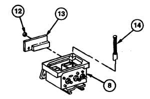
Remove brush and spring assembly (14) from regulator housing (8). 8. Remove three nuts (12) and diode trio (13) from regulator housing (8). 9. 
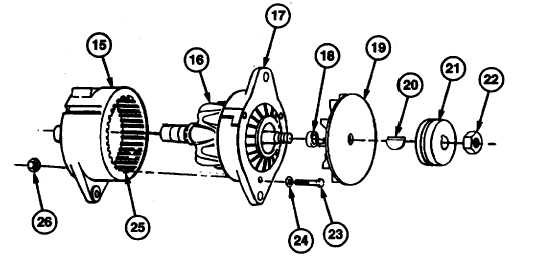
Remove nut (22), groove pulley (21), and fan holder assembly (19) from shaft of rotor (16). 10.  Remove Woodruff key (20) and spacer (18) from shaft of rotor (16). NOTE Make sure stator remains in slip ring end housing. 11.  Remove three screws (23), nuts (26), and washers (24), drive end housing (17), and rotor (16) from stator (25) and slip ring end housing (15). 3-85

Privacy Statement - Press Release - Copyright Information. - Contact Us - Support Integrated Publishing

Integrated Publishing, Inc. - A (SDVOSB) Service Disabled Veteran Owned Small Business