|
| |
TM 9-2330-398-24
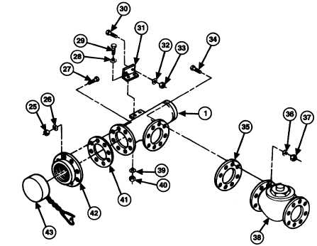
2-123. FLOW CONTROL VALVE AND FLANGE ASSEMBLY REPLACEMENT (continued).
10.
Remove cap (43) from coupling (42).
11.
Remove eight screws (27), washers (26), and self-locking nuts (25), and coupling (42) and gasket (41) from flange
assembly (1). Discard self-locking nuts and gasket.
12.
Remove eight screws (34), washers (36), and self-locking nuts (37) from precheck valve (38) and flange assembly
(1).
13.
Remove two screws (29), four washers (28 and 39), and two self-locking nuts (40) and flange assembly (1) and
gasket (35) from bracket (31) and precheck valve (38). Discard self-locking nuts and gasket.
14.
Remove two screws (30), washers (32), and self-locking nuts (33) and bracket (31) from semitrailer. Discard self-
locking nuts.
b. INSTALLATION
1.
Install bracket (31) on semitrailer with two screws (30), washers (32), and new self-locking nuts (33).
2.
Install flange assembly (1) and new gasket (35) on precheck valve (38) with eight screws (29), washers (28 and
39), and new self-locking nuts (40).
NOTE
Do not tighten screws until after all connections are made.
3.
Install flange assembly (1) and precheck valve (38) on bracket (31) with two screws (30), four washers (28 and
39), and two new self-locking nuts (40).
2-268
|