|
| |
TM 55-2915-335-30&P
2-24. IMPELLER HOUSING - lNSPECT/REPLACE (Cont)
2-24
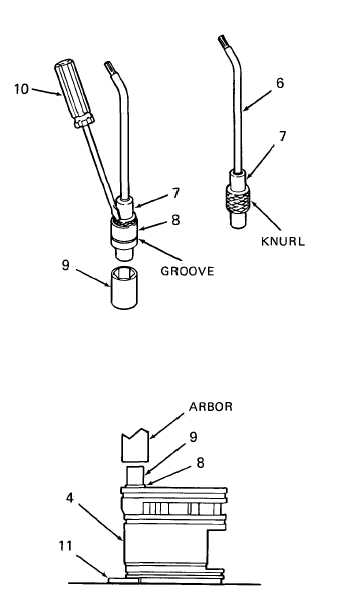
4. REPLACE POSITIVE TERMINAL
a. Cut a 4-inch (100 mm) length of lead wire (6)
(Item 3, Appendix B, Bulk Items List). Strip in-
sulation back about 1/4 inch (6 mm) at one end.
Tin bare end with solder (Item 8, Appendix C).
b. Install tinned end of wire (6) in terminal pin (7),
as shown. Heat terminal with soldering iron to
bond lead wire to terminal. Check for good bond
by tugging on lead wire.
c. Apply one drop of locking compound (Item 5,
Appendix C) to knurl of terminal pin (7). Place
terminal pin (7) in terminal housing (8). Place
terminal housing (8) into a 5/16 inch socket (9) or
equivalent. Press terminal pin (7) into terminal
housing (8) using a small screw driver (10). Ter-
minal pin (7) is fully inserted into terminal hous-
ing when end of pin protrudes through housing.
d. TI INSPECT. Inspect solder joint to make sure it
is secure. Check that terminal pin is fully posi-
tioned in terminal housing.
e. Insert primary lead wire (6) into terminal bore in
impeller housing (4) and through wire port in im-
peller housing. Place impeller housing on hand
operated arbor press, as shown. Make sure area
under primary terminal bore is supported. It may
be necessary to place a flat metal washer (11) be-
tween impeller housing and arbor plate to support
the outer edge below the terminal.
GO TO NEXT PAGE
2-91
|

