|
| |
TM 55-2915-335-30&P
2-23. ELECTRICAL CIRCUITS - lNSPECT/REPLACE (Cont)
2-23
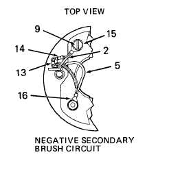
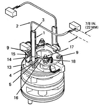
c. Install Negative Secondary Brush Circuit
(1)
(2)
(3)
(4)
Pre-cut leads of capacitor (13) and fuse (14).
For both capacitor and fuse, cut one lead off
at 3/8 inch (9,5 mm). Cut the other off at 7/8
inch (22 mm).
Twist short leads of capacitor and fuse
together. Use heat sinks on both sides of
solder joint. Solder leads together with rosin-
core solder (Item 8, Appendix C).
Cut about 6 inches (152,4 mm) of new lead
wire (2) (Item 3, Appendix B, Bulk Items
List). Strip 1/4 inch (6,4 mm) of insulation
from one end. Crimp long lead of fuse (14)
and lead wire (2) together in terminal (15).
Secure terminal to brush card with screw (9)
as shown.
If shrink tube (4) was removed, replace it. In-
stall a 3/4 inch (19 mm) length of shrink tube
over base of stud. Use l/4-inch shrink tube
(Item 2, Appendix B, Bulk Items List).
Position lead wire on mounting stud as
instructed. Failure to position lead cor-
rectly will cause improper alignment of
the field tube. This could lead to early
pump failure.
(5) Install a 2-1/4 inch (57 mm) length of shrink
tube (1) over mounting stud and lead wire.
Use 1/4-inch shrink tube (Item 2, Appendix
B, Bulk Items List). Position lead wire exactly
as shown in top view of negative secondary
brush circuit. Push shrink tube down to about
1/4 inch from shrink tube (4). Use heat gun
to shrink lead wire in place on stud.
NOTE
If reusing secondary brush, do not trim
shunt leads. Brush away used solder and
re-tin lead.
GO TO NEXT PAGE
2-84
|


