|
| |
TM 5-4320-306-24
3-6. REPLACE ENGINE ASSEMBLY (Continued)
NOTE
RUN/STOP lever must be in full run position (toward cooling blower).
7.
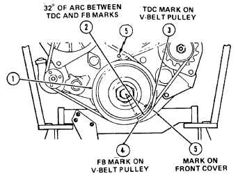
Measure on the V-belt
pulley (1) circumference
32 degrees (2.700 inches
or 68 mm) of arc (2)
clockwise from TDC mark
(3) and point on the V-belt
pulley (4). This is the Fuel
Beginning (FB) or com-
mencement of injection
flow point and, when
aligned with the roll pin
above the V-belt pulley,
indicates that the fuel in-
jection pump is just star-
ting to feed fuel to the
injectors.
WARNING
Death or serious injury could occur if diesel fuel oil Is not handled carefully. Use in a
well-ventilated area away from open flame, arcing equipment, ignition sources,
heaters, or excessive heat. Always store fuel in proper, marked containers. DO NOT
SMOKE.
8.
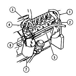
Disconnect overflow line (1) from the injection
pump and plug overflow port (2).
9.
Disconnect the cylinder one injection line (3)
from the injection pump. Connect stub pipe
(4) to the cylinder one output connector of the
injection pump.
10. Connect the delivery pipe of high pressure
timing device No. 003-0714 (5) to fuel inlet
port (6) of the fuel injection pump.
11. Connect suction pipe of high pressure timing
device No.003-0714 (5) to fuel line from fuel
tank.
3-30 Change 1
|


