|
| |
TM 5-4320-306-24
3-6. REPLACE ENGINE ASSEMBLY (Continued)
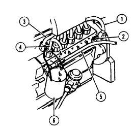
12. Position fuel reservoir No 003-0777 (7) under stub pipe (4) so that fuel runs into reservoir during injection timing test
and adjustment.
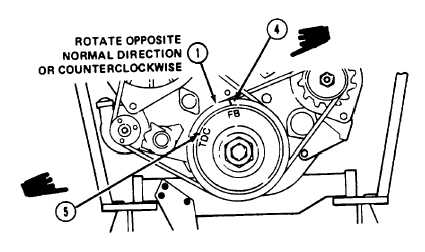
13. Rotate V-belt pulley (1) counterclockwise until the FB mark (4) is approximately 90 degrees before engine TDC (5).
14. Pump hand pump handle of high pressure
timing device No. 003-0714 (5) until fuel flows
out of stub pipe (4) into reservoir (6)
15. Rotate V-belt pulley clockwise (in normal running direction) slowly and continue to pump hand pump handle until fuel
flow decreases to a drip. When the interval between droplets is 5 to 8 seconds, the fuel injection rate is correct. Stop
rotation of crankshaft.
16. Make sure mark FB lines up with marking on front cover. If so, the fuel injection timing is adjusted correctly and
there is no need for further adjustment. If not, proceed with the following steps to adjust fuel injection timing.
Change 1 3-31
|