 |
|||
|
|
|||
|
Page Title:
Coolant Temperature Safety Switch |
|
||
| ||||||||||
|
|
 TM 5-4320-258-34
d.
Reassembly.
(3) Use a puller to remove the impeller (6)
from the shaft, taking care to prevent damage to the
(1) Reassemble the water pump as shown
casting.
in figure 3-8.
(4) To remove. the water pump shaft (10)
(2) Apply a light film of grease to the face
from the housing (12), remove the retaining ring (9) and
of the seal to facilitate sealing and seating.
press on the impeller end of the shaft to press the shaft
(3) When assembling the seal and shaft,
out of the fan end of the housing. Pressing the fan out
apply a thick coating of soap suds to the parts to prevent
in the opposite direction will severely damage the
damage to the seal.
e. Installation. Install the water pump on the
housing.
c. Cleaning and Inspection.
engine (TM 5-4320-258-12).
3-9.
Coolant Temperature Safety Switch
(1) Discard and replace seals, gaskets, and
a. Removal.
all parts contained in the water pump repair' kit. Clean
all remaining parts with cleaning solvent (FED. Spec.
(1) Disconnect the electrical leads from the
P-D-680); dry thoroughly.
coolant temperature switch. Tag leads to facilitate
(2) Inspect the water pump housing for,
reassembly.
cracks, distortion, and scoring of the seal contact
(2) Disconnect the coolant temperature
surface. Replace the entire water pump if housing is
safety switch sender from the engine.
dam- aged. (3) Inspect all other parts for cracks, worn
(3) Remove the coolant temperature safety
or damaged threads, distortion, and other damage;
switch from the control panel (see items 1 through 4, fig.
replace damaged parts.
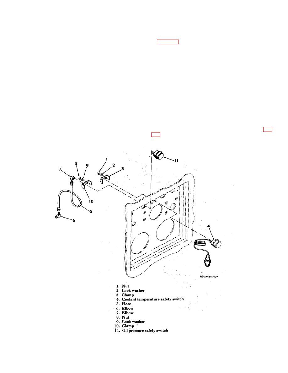
Figure 3-9.Coolant temperature and oil pressure safety switches, exploded view.
3-13
|
|
Privacy Statement - Press Release - Copyright Information. - Contact Us |
