 |
|||
|
|
|||
|
|
|||
| ||||||||||
|
|
 TM 5-4320-258-34
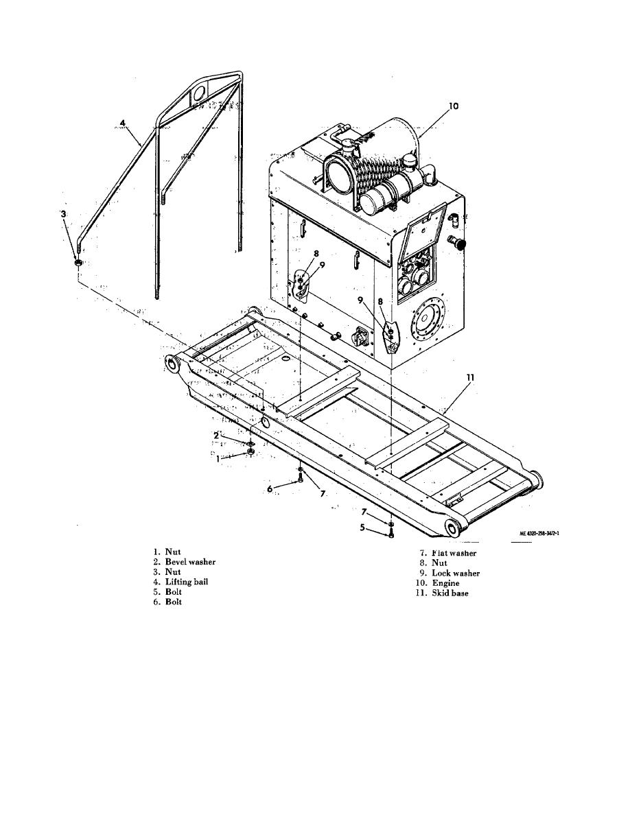
Figure 2-1. Engine removal.
(5) Remove the bolts (5 and 6), flat
(2) Connect the battery cables to the
washers (7), nuts (8), and lock washers (9) that secure
battery and to the engine. Review the caution in
the engine to the skid base. Use a suitable lift truck to
subparagraph a above to prevent damage to the
lift the engine from the skid base, taking care to insert
components of the electrical system while connecting
the forks under structural members only.
the battery cables.
b. Installation.
(3) Install the fuel lines connecting the
engine to the fuel tank.
(1) Use a lift truck to position the engine on
(4) Position the lifting bail (4) on the skid
the skid base (11). Take care to insert the forks under
base; secure with nuts (1) and bevel washers (2).
structural members only. Secure the engine to the skid
(5) Install the centrifugal pump TM 5-4320-
base with bolts (5 and 6), nuts (8), lock washers (9), and
258-12)
flat washers (7).
2-4
|
|
Privacy Statement - Press Release - Copyright Information. - Contact Us |