 |
|||
|
|
|||
|
Page Title:
Section III - OPERATION OF EQUIPMENT |
|
||
| ||||||||||
|
|
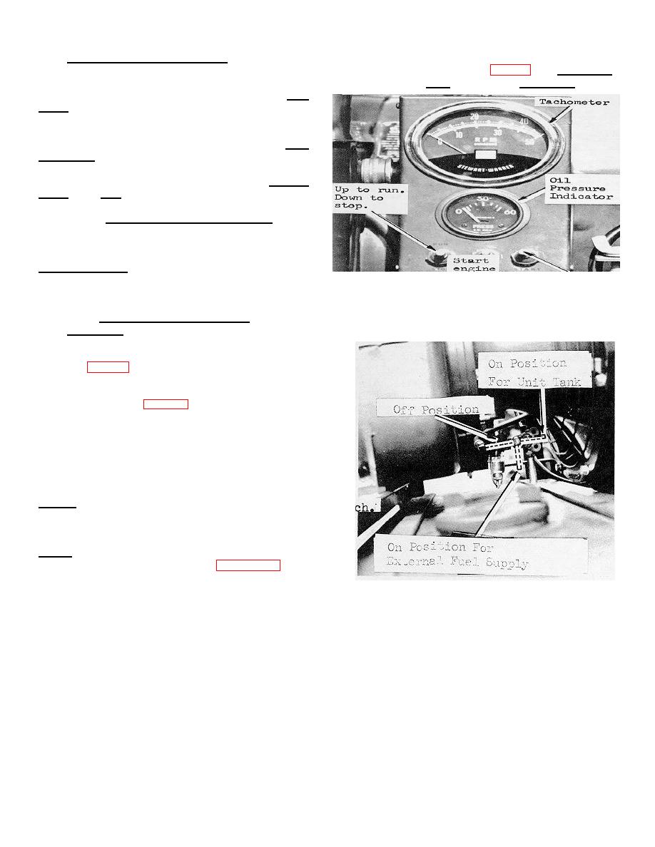 2-9. CONTROIS AND, INSTRUMETS
The controls and instruments for the pumping assembly are all contained in the control panel (fig. 2-2). The tachometer
monitors the engine speed and should normally read 3200 rpm. The oil pressure gage illustrates the oil pressure of the
engine and has a normal reading of 40-50 psi. The start
switch engages the starter when it is pressed down. The
engine is equipped with a magneto, there-fore, no
electric current is required from the battery or alternator
to energize the ignition to run the engine. With the run-
stop switch in the run position and the oil pressure
switch depressed, the magneto has a complete circuit
and can energize the ignition system. With the run-stop
switch in the stop position, the magneto is grounded and
cannot energize the ignition system. The engine is
equipped a low oil pressure shutoff switch which
performs the function of stopping the engine Of the oil
pressure falls below 20 psi and will not allow the engine
to start until it has produced 25 lbs. oil pressure. The
oil pressure switch on the control panel will override the
low oil pressure cutoff when it is depressed.
FIGURE 2-2. CONTROL PANEL
Section III - OPERATION OF EQUIPMENT
2-10. STARTING
1. Perform necessary daily preventative maintenance
services for the pumping assembly
2. Open vent on inside of fuel tank cap.
3. Move fuel shutoff to proper position for fuel source
being used (Fig. 2-3).
4. Check air cleaner inlet temperature control and oil
baffle control for proper setting (TM 5-2805-259-
14),Improper setting of inlet temperature and oil baffle
controls can cause overheating and damage to the
engine.
5. Move run-stop switch to run position.
6. Depress oil pressure switch and start switch.
NOTE: If the engine does not start after approx. 20 seconds,
release switch and allow unit to stand for a 10 minute cooling off
period. If unit does not then start, refer to TM 5-2805-259-14 to
determine cause.
NOTE: The governor has been preset to 3200 RPM, making
additional adjustment unnecessary. FIGURE 2-3 FUEL SHUT-
OFF VALVE The choke is located at the front of the engine & is
electrically operated, making manual choking unnecessary.
FIGURE 2-3. FUEL SHUT-OFF VALVE
-8-
|
|
Privacy Statement - Press Release - Copyright Information. - Contact Us |
