 |
|||
|
|
|||
|
Page Title:
Section II - PREOPERATIVE INSTRUCTIONS |
|
||
| ||||||||||
|
|
 Section II - PREOPERATIVE INSTRUCTIONS
2-6. SELECTION OF SITE
1.
Keep the unit close to water source, with a vertical suction lift of 25 feet or less.
2.
Avoid a muddy, dusty, or sandy site. If it is necessary to install the unit on soft ground, arrange a foundation
of planking, logs, or concrete.
3.
Lock the support leg in the down position.
4.
Keep the unit as level as possible.
5
Securely chock wheels to obtain maximum rigidity.
WARNING: Provide adequate ventilation or pipe the exhaust gases to the outside if operating unit in a closed area.
2-7. ATTACHMENT OF HOSE
A.
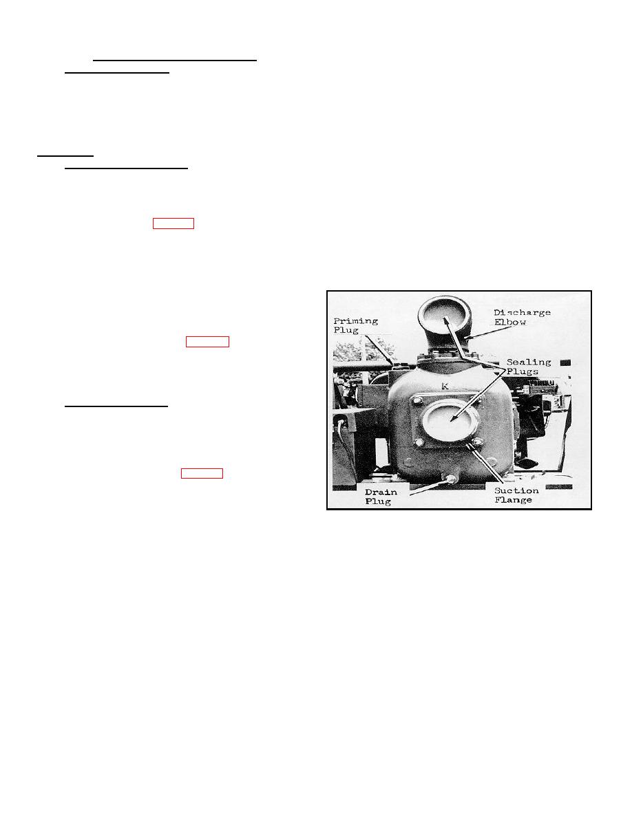
SUCTION LINIE - CAUTION: Attach a suitable strainer before operating pump. The pump inlet connection
is a 4 in. NPT. Use 4 in. reinforced noncollapsible suction hose of rigid plastic, aluminum or steel pipe. Clean all
threads and coat them with a pipe Joint compound or water-proof grease. Plastic sealing plugs are used in the suction
and discharge ports for shipping purposes, and may be saved for future use. Remove sealing plugs and insert suction
line into suction flange (fig. 2-1). All fittings and joints must be fully tightened and air tight. If suction line is not
completely air-tight, the pump will not properly complete the priming cycle and deliver water. Install suction strainer at
lower end of suction line to prevent debris and abrasive liquids from entering pump. Provide a settling bed to prevent
sand from entering pump during surf operations. Slope line downward into water course without any kinks or humps to
trap air. Submerge lower end of suction line in water source being careful to avoid any obstruction of the suction line or
vortex because of insufficient submergence.
B.
DISCHARGE LINE - The discharge connection
(both the flange and elbow) is 4" NPT. Clean all threads & coat
them with a pipe Joint compound or water-proof grease.
Remove sealing plug and insert the discharge line (4" hose or
pipe) into the discharge elbow (Fig. 2-1) and tighten securely.
Avoid kinks so as to allow free upward excape of air being
expelled during the priming cycle. Do not restrict any point of
the discharge line while the pump is in the priming cycle.
2-8. PRIMING OF PUMP - Priming must be done before
starting the engine, or the mechanical seal will be damaged or
destroyed, preventing operation of the unit. Although the pump
is generally referred to as a "self-priming" pump, it will only
prime when the pump casing has a proper internal water level.
To prime the pump, fill the casing with water after removal of
the pipe plug atop the casing (Fig. 2-1). After the casing is at
least 2/3 full replace the pipe plug and tighten completely.
FIGURE 2-1. PRIMING & ATTACHT OF HOSE
-7-
|
|
Privacy Statement - Press Release - Copyright Information. - Contact Us |
