 |
|||
|
|
|||
|
|
|||
| ||||||||||
|
|
 CHAPTER 1
INTRODUCTION
1-1. SCOPE
In this manual will be found the suggested procedures for the operation of the pump, recommendations for
preventative maintenance, general service, and repair. This manual covers only those parts that are assembled and/or
installed by the manufacturer. TM 5-2805-259-14, is furnished for maintenance instructions of the engine.
1-2. DESCRIPTION
A.
contained, trailer mounted, self-priming unit. This pumping unit is for pumping water, with performances in the range as
shown on the plate atop the battery box. The unit has 4" NPT inlet and 4" NPT outlet with a rated capacity of 600 GPM
at50 ft TDH. The unit is powered by a four-cylinder gasoline engine directly coupled to the pumping assembly.
Instruments and controls necessary for operation of the unit are mounted on the control panel (Fig. 2-2).
B.
ENGINE - Refer to TM 5-2805-259-14 for a description of the Military Standard engine, Model No. 4A084-III.
C.
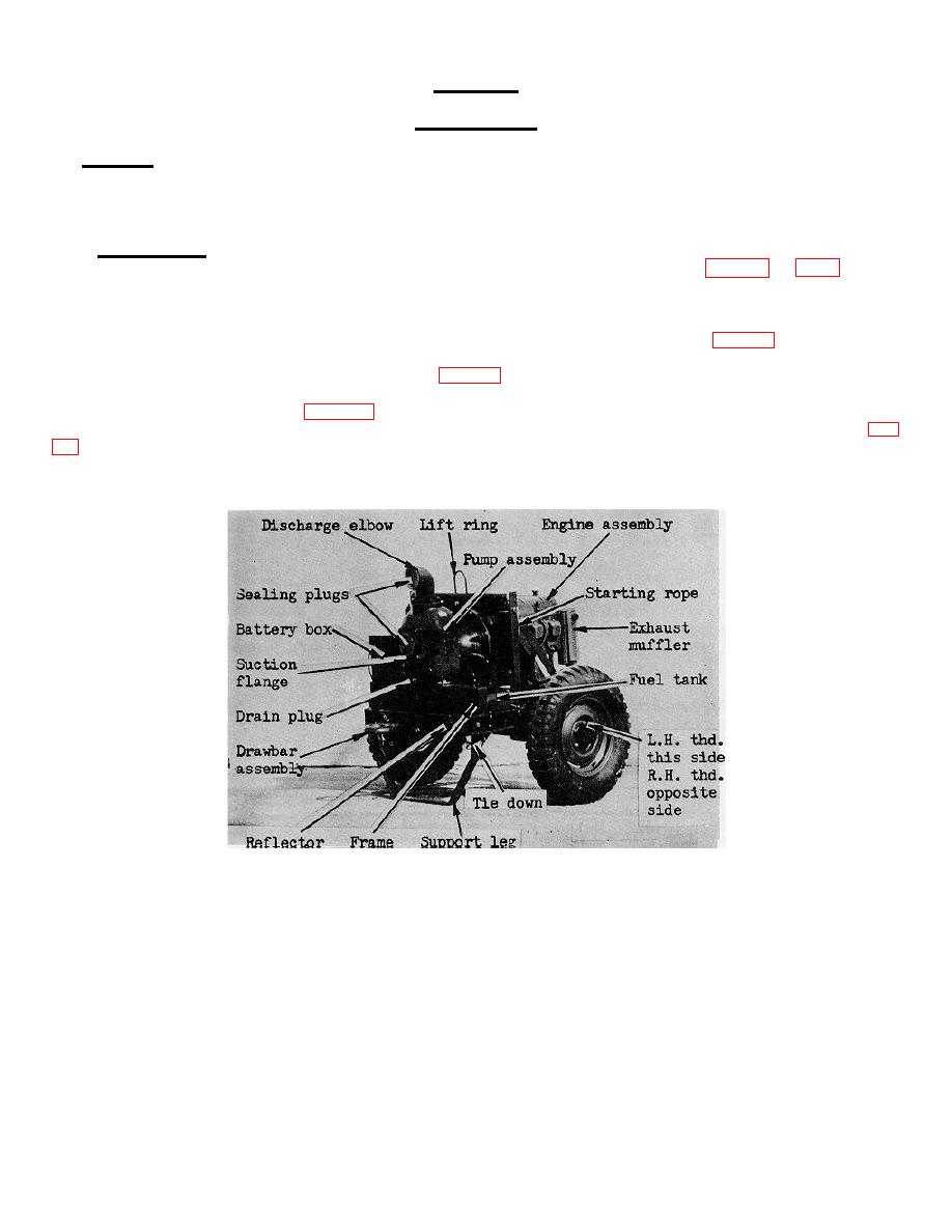
PUMP ASSEMBLY - The pump assembly (Fig. 1-1) is a four inch conventional type self-priming centrifugal
pump designed to deliver 600 GPM at 50 ft. TDH.
D.
TRAILER - The trailer (Fig. 1-1) is constructed of welded steel members and is equipped with two wheels
with pneumatic tires and an axle for towing at speeds up to 30 MLPH on surfaced roads. A collapsible support leg (fig.
1-1) is provided at rear of the trailer to support the unit during operation. The trailer is equipped with. a removable
drawbar for towing.
FIGURE 1-1. PUMPING, ASSEMBLY, LEFT REAR 3/4 VIEW
-1-
|
|
Privacy Statement - Press Release - Copyright Information. - Contact Us |