 |
|||
|
|
|||
|
Page Title:
NO WATER DISCHARGE OR INSUFFICIENT DISCHARGE |
|
||
| ||||||||||
|
|
 3-7. PUMP FAILS T0 START
Probable cause
Possible remedy
Possible remedy
speed should be 3600 rpm. Adjust
Probable cause
engine speed if incorrect (TM 5-
2805-259-14).
Battery weak or dead
Service battery and recharge, or
replace battery if defective (par.
Disassemble and clear obstruction
Impeller clogged
3-14).
TM 5-2805-259-14,
Refer to
Engine defective
Impeller broken, dam-
Replace impeller (par. 3-23).
Impeller frozen
Clean or replace impeller (par. 3-
aged, or worn
23).
Suction hose faulty
Replace suction hose if rubber in-
Impeller clogged or
Disassemble and clear obstruction
ner line has collapsed.
jammed
Clear strainer and suction line.
Suction line or
strainer clogged
3-8. NO WATER DISCHARGE OR INSUFFICIENT
DISCHARGE
Probable cause
Possible remedy
Possible remedy
Probable cause
Tighten or replace impeller (par.
Impeller loose, bro-
3-23) .
ken, or damaged
Remove discharge elbow at pump
Discharge check valve
pump bearing defective Replace bearing (par. 3-23).
discharge flange and clean de-
not seating
Refer to engine manual, TM 5-
Engine bearing
p o s i t s from around discharge
defective
valve. If gasket is worn in area
2805-259-14.
where check valve seats, replace
damaged gasket.
Move pump closer to water source.
Excessive suction lift
Probable cause
Possible remedy
Check all suction hose and line
Leak in suction line
connections, all exhaust primer
Tighten connections.
Suction or discharge
line connections, and exhaust
connections loose
primer valve for air-tight condi-
Tighten bolts.
Bolts on flanged joints
tion.
loos e
Exposed suction intake Submerge suction intake.
Replace gaskets (par. 3-23).
Seal defective
Make sure engine speed control is
Engine speed too low
Replace gaskets (par. 3-23).
Gaskets defective
in governed position. Check ta-
Repair or replace pump (par. 3-20
Pump body defective
chometer with pump in operation;
or 3-23).
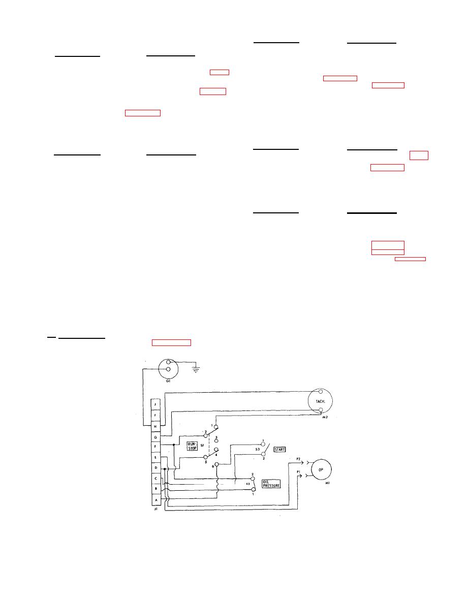
Section IV. ELECTRICAL SYSTEM
trol panel provides controls and instruments for start-
i n g , stopping, and monitoring the operation of the
a . Control Panel. An electrical schematic diagram
e n g i n e . The RUN-STOP switch is connected to the
engine magneto, allowing it to provide spark for the
of the control panel is given in figure 3-3. The con-
|
|
Privacy Statement - Press Release - Copyright Information. - Contact Us |
