 |
|||
|
|
|||
|
Page Title:
Section II. MOVEMENT TO NEW WORKSITE |
|
||
| ||||||||||
|
|
 2-5. INSTALLATION OR SETTING UP
b . Connect the suction line to the intake port and the
INSTRUCTIONS
discharge line to the discharge port. If a hose is
used for the suction line, it should be a rigid-walled
a . Locate the pump
as near to the liquid source as
t y p e in order to prevent collapsing under suction.
practicable. Select a
location which is as level as
Carefully seal and tighten all connections in the suc-
p o s s i b l e in order to
insure proper engine servicing
tion line to prevent air leaks. Even a slight leak will
a n d pump operation.
If necessary, set the pump on
will greatly reduce pumping efficiency.
s u p p o r t s in order to
compensate for uneven terrain.
c . Connect a strainer to the end of the suction line
W a r n i n g . Do not operatethe pump in an enclosed
to prevent foreign matter from entering the line.
area. Exhaust fumes contain carbon mon-
Caution. Do not operate the pump without a strainer
o x i d e , a clear, odorless, poisonous gas.
Inhalation of exhaust fumes will result in
o n the end of the suction line. Entry of
foreign matter will damage the impeller.
serious illness or death.
Section II. MOVEMENT TO NEW WORKSITE
prevent entry of foreign objects or thread damage dur-
2-6. DISMANTLING FOR MOVEMENT
ing shipment.
a . Clean all mud and dirt from the exterior of the
pump with water. Remove greasy or gummy deposits
c . Remove the drain plug (fig. 2-5) at the bottom
w i t h a cloth dampened with an approved cleaning
of the pump housing to drain all fluid from the pump.
solvent.
b . Disconnect suction and discharge hoses from their
Reinstall the pump as described in paragraph 2-5.
respective ports. Install plugs in adapter ports to
Section III. CONTROLS AND INSTRUMENTS
pump. model 62-1/2E13-4A084.
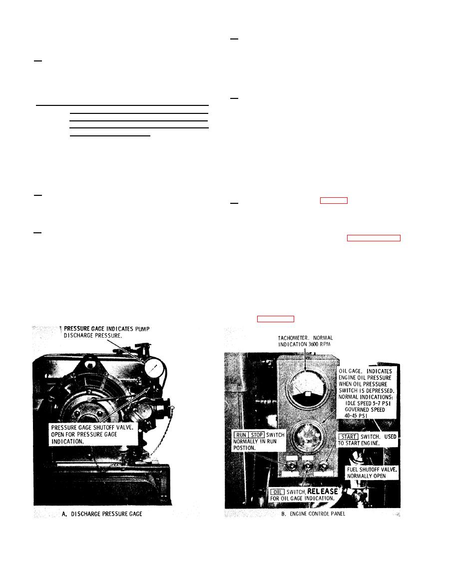
2-9. CONTROLS AND INSTRUMENTS
This section describes, locates, illustrates, and
f u r n i s h e s operator, crew, or maintenance personnel
The purpose of controls and instruments is illus-
sufficient information about various controls and
t r a t e d in figure 2-2.
i n s t r u m e n t s for proper operation of the centrifugal
|
|
Privacy Statement - Press Release - Copyright Information. - Contact Us |
