 |
|||
|
|
|||
|
Page Title:
CHAPTER 2. INSTALLATION AND OPERATION INSTRUCTIONS |
|
||
| ||||||||||
|
|
 INSTALLATION AND OPERATION INSTRUCTIONS
Section I. SERVICE UPON RECEIPT OF EQUIPMENT
c . Set the RUN-STOP switch in the STOP position
to prevent starting, and manually rotate the starting
pulley of the engine several turns to assure that the
Carefully unload the crated pump, using a lift truck
engine has not seized and that the pump impeller
or other suitable means. Take care to prevent piercing
rotates freely without scraping or binding.
crates with forks of truck.
d. Perform all daily preventive maintenance services
for the engine described in TM 5-2805-259-14.
Remove the wooden crate carefully. Do not allow
pry bars, used for crate removal, to penetrate crate
COMPONENTS
interior. This could damage pump unit.
a . The dry-charged, lead-acid storage battery is
shipped mounted in the battery box, but the electrolyte
is shipped separately. Add electrolyte to each cell
a. Inspect the pump for obvious damage which might
in the dry-charged battery until the electrolyte level
have occurred during shipment.
is above the battery plates. Do not overfill the battery.
b . Inspect for loose or missing nuts, bolts, and other
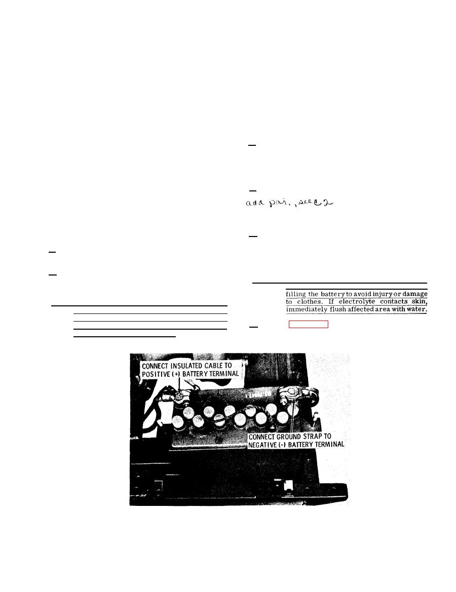
Warning. The electrolyte for the dry-charged battery
attaching hardware. Check the suction and discharge
consists of sulphuric acid. Use care when
ports for damaged threads.
Note. The pump has been tested prior to shipment.
Since gaskets have a tendency to dry and
shrink after testing, make especially sure
b . Refer to figure 2-1 and connect battery cables;
that all bolts on gasket joints are tight in
replace cover.
order to prevent pump leakage.
|
|
Privacy Statement - Press Release - Copyright Information. - Contact Us |
