 |
|||
|
|
|||
|
|
|||
| ||||||||||
|
|
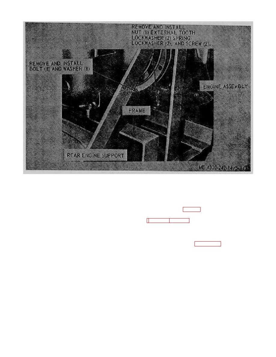
 Figure 5-3. Engine, removal and installation (Sheet 2 of 2).
5-6. Pump
(9) Remove the suction manifold and strainer
body assembly (fig. 5-1 (1) ).
a. General. The pump or engine may be removed
from the trailer frame separately.
(10) Remove the discharge manifold, elbow
and check valve. (fig. 5-2).
b. Removal.
(11) Remove the tank to carburetor fuel line
(1) Remove starting switches electric cable
(fig. 4-4).
(12) Connect a suitable lifting device to the
(2) Remove throttle control line.
pump.
(3) Remove tachometer hourmeter cable and
(13) Disconnect battery cables.
clip.
(14) Refer to figure 5-4 and remove the
(4) Remove pump suction line.
mounting hardware and lift the pump assembly from the
(5) Remove pump pressure line.
trailer frame assembly.
(6) Remove engine oil pressure lines.
c. Installation. Installation of pump assembly is
(7) Remove instrument panel.
reverse procedure of removal.
(8) Remove
bolt
lockwasher
from
intermediate housing and flywheel guard.
5-7
|
|
Privacy Statement - Press Release - Copyright Information. - Contact Us |