 |
|||
|
|
|||
|
|
|||
| ||||||||||
|
|
 (4) Remove the engine oil pressure gage (fig.
(1) Install the pump discharge pressure gage,
4-4).
pump suction gage, and lines (fig. 4-4).
(5) Remove the pump discharge pressure
(2) Install the engine oil pressure gage (fig. 4-
gage (fig. 4-4).
4).
(6) Refer to figure 4-4 and remove the panel
(3) Install the tachometer-hourmeter (fig. 4-
and frame.
4).
b. Cleaning and Inspection. Clean and inspect all
(4) Install the starting switches (fig. 4-4).
parts. Replace a defective part.
(5) Install the throttle cable (fig. 4-3).
c. Installation. Refer to figure 4-4 and install the
panel and frame.
Section IX. PUMP ASSEMBLY
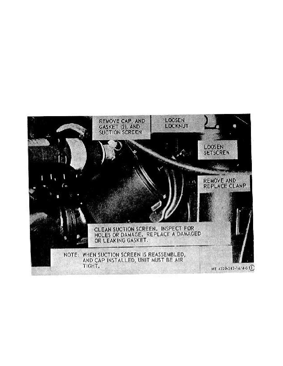
4-24. Suction Screen
Refer to figure 4-5 and remove, clean, inspect, and
install suction screen.
Figure 4-5. Suction screen, removal and installation. Serial numbers 371201 through 415493
and model US36ACG Serial numbers 37044-001 through 37044-240. (Sheet 1 of 2).
4-12
|
|
Privacy Statement - Press Release - Copyright Information. - Contact Us |
