 |
|||
|
|
|||
|
|
|||
| ||||||||||
|
|
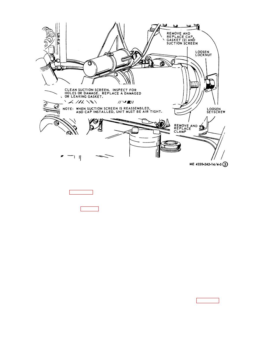 Figure 4-5. Suction screen, removal and installation. Serial numbers 419501 through
419959. (Sheet 2 of 2).
4-25. Air Eliminator Assembly
(4) Inspect all fittings and screws for damage.
Replace any defective parts as necessary.
air eliminator assembly.
(5) Discard the gasket and use a new gasket
for reassembly.
b. Disassembly.
(6) Inspect the valve and seat for wear,
(1) Remove hose (10, fig. 4-7), hose clamp
grooves, or ridges. Replace the valve and seat as an
(9), air venting valve (8), pipe coupling (7), pipe nipple
assembly if worn or damaged.
(6), pipe plug (4), and ball (3).
d. Reassembly.
(2) Remove nuts (20), lockwashers (21), and
capscrews (1 and 51.
(1) Assemble valve lever clip (12, fig. 3-11)
and seat (14) to cap (2).
(3) Remove cap assembly from discharge
elbow (19). Remove gasket (11).
(2) Assemble valve lever (16) to float
assembly (18) with screw (22).
(4) Remove valve retainer (17), pivot (13),
and valve (15).
(3) Install valve (15), valve retainer (17), and
pivot (13).
(5) Remove screw (22), separating valve
lever (161 and float assembly (18).
(4) Install a new gasket (11) and cap
assembly on discharge elbow (19).
(6)
Remove seat (14) and valve lever clip
(12) from cap (2).
(5) Install capscrews (1 and 5), lockwashers
(21), and nuts (20).
c. Cleaning and Inspection.
(6) Install ball (3), pipe plug (4), pipe nipple
(1) Clean all parts with cleaning solvent
(6), pipe coupling (7), air venting valve (8), hose (10),
PD680 and wipe dry with a clean, lintless cloth.
and hose clamp (9).
(2) Inspect the cover for cracks and breaks.
Replace a defective cover if necessary.
air eliminator assembly.
(3) Inspect the float assembly for holes and
cracks. Replace a defective float assembly.
4-13
|
|
Privacy Statement - Press Release - Copyright Information. - Contact Us |
