 |
|||
|
|
|||
|
Page Title:
Figure 4-4. Gages and panel, removal and installation. (Sheet 2 of 2). |
|
||
| ||||||||||
|
|
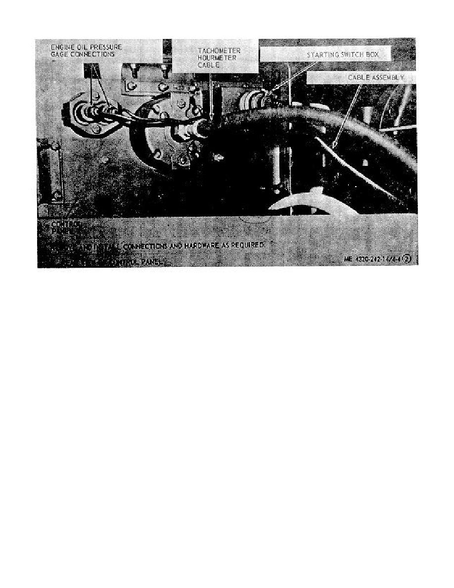 Figure 4-4. Gages and panel, removal and installation. (Sheet 2 of 2).
4-22. Pump Gages and Lines
4-20. Tachometer-Hourmeter
a. Removal. Refer to figure 4-4 and remove the
a. Removal. Refer to figure 4-4 and remove the
tachometer-hourmeter.
pump discharge pressure gage, pump suction gage, and
lines.
b. Cleaning and Inspection. Clean with cleaning
b. Cleaning and Inspection.
solvent PD-680 and inspect all parts. Replace a
defective tachometer-hourmeter.
(1) Clean and inspect all parts. Replace a
c. Installation. Refer to figure 4-4 and install the
defective gage.
tachometer-hourmeter.
(2) Clean and inspect hoses and fittings.
Replace a hose assembly if hose is defective or fitting is
4-21. Engine Oil Pressure Gage
cross-threaded.
a. Removal. Refer to figure 4-4 and remove the
c. Installation. Refer to figure 4.4 and install the
engine oil pressure gage.
pump gage and lines.
b. Cleaning and Inspection. Clean all parts with
cleaning solvent PD-680. Inspect the case for cracks
4-23. Panel and Frame
and dents. Inspect threads for damage. Replace a
a. Removal.
defective engine oil pressure gage.
(1) Remove the throttle cable (fig. 4-31.
c. Installation. Refer to figure 4-4 and install the
(2) Remove the starting switches (fig. 4-4).
engine oil pressure gage.
(3) Remove the tachometer-hourmeter (fig.
4-4).
4-11
|
|
Privacy Statement - Press Release - Copyright Information. - Contact Us |
