 |
|||
|
|
|||
|
Page Title:
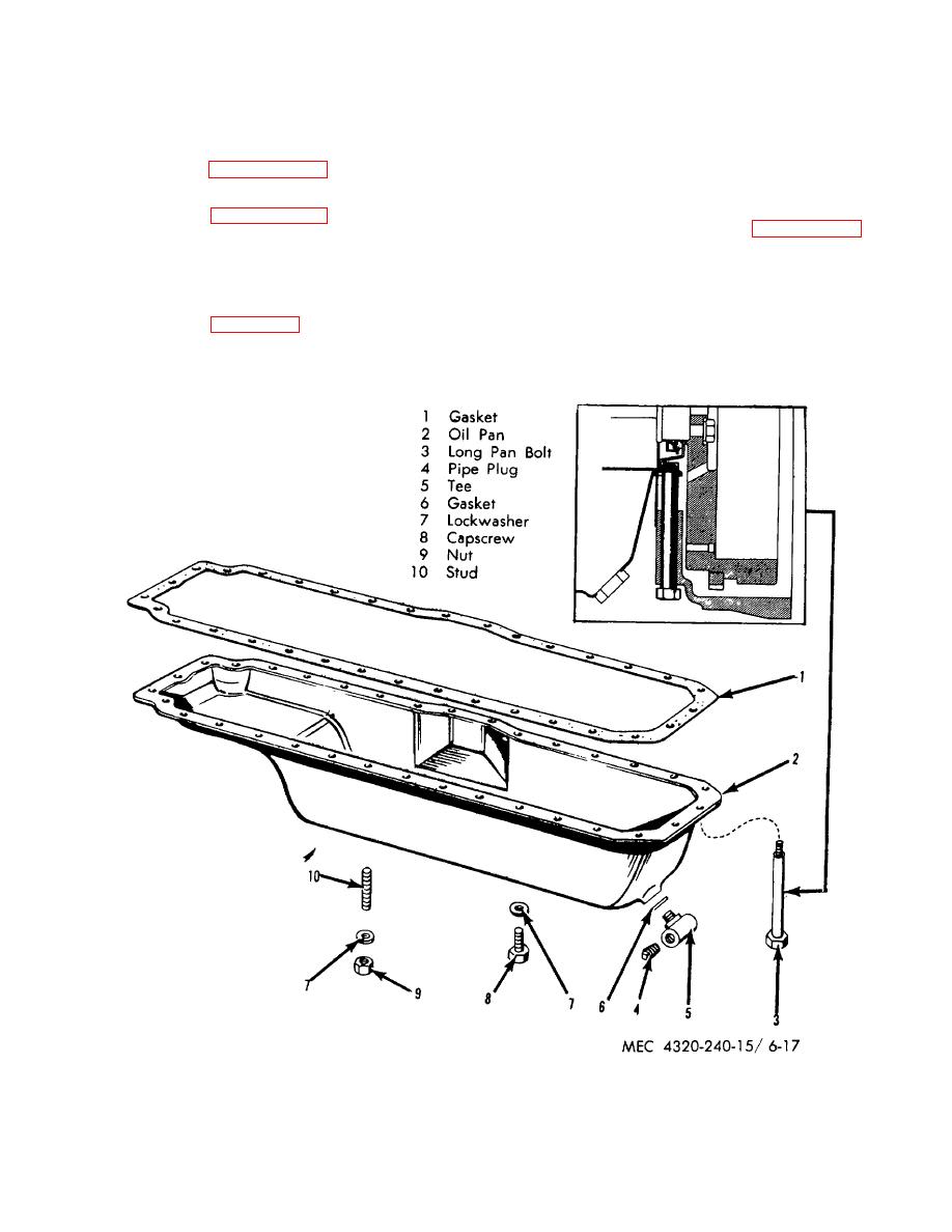
Figure 6-17. Oil pan-exploded view. |
|
||
| ||||||||||
|
|
 connecting rod; remove the cap (18) and sleeve bearing
basic function is to transmit energy to the crankshaft.
(19).
b. Removal.
(5) Push the-assembled rod and piston up
through the top of the block. While pushing the piston
and rod from the block be very careful the connecting
(1) Refer to paragraph 6-15b and remove the
rod does not scratch the cylinder wall.
oil pump.
(2) Refer to paragraph 6-12b and remove the
c. Disassembly.
Refer to figure 6-19 and
cylinder head.
disassemble connecting and piston assembly.
(3) Ream the ridge off the top of each
Disassemble the pistons and connecting rods in sets
cylinder bore with a standard ridge reamer. Blow metal
and keep the sets together. Also be sure each piston
fragments from the cylinder with compressed air.
rod assembly is reinstalled in the cylinder from which it
was removed.
(4) Refer to figure 6-19 and remove the two
nuts (27) that secure a connecting rodcap
to a
Figure 6-17. Oil pan-exploded view.
6-16
|
|
Privacy Statement - Press Release - Copyright Information. - Contact Us |