 |
|||
|
|
|||
|
|
|||
| ||||||||||
|
|
 TM 5-4320-234-34
(a) Temporarily insert the camshaft (19,
(15) Install the cylinder head (para 4-3c).
fig. 43) into the block. Check the clearance between
4-11. Camshaft.
the camshaft bearing journals and camshaft bearings
a. Removal. With the engine removed from the pump
(20, 21, 22, and 23) with feeler stock cut in strips 1/4
assembly and mounted on an engine stand, proceed as
inch (0.6250 cm) wide. Dress the feeler stock with a
follows:
stone to eliminate burrs or feathered edges. Clearance
(1) Remove the cylinder head (para 4-3a).
between bearings and journals must be between 0.002
(2) Remove the valves and valve tappets
(0.0050 cm) and 0.004 (0.0100 cm) inch.
(para 44b).
(b) If clearance exceeds tolerances,
(3) Remove the gear cover (para 4-7a).
remove the camshaft and replace the camshaft
(4) Remove the nut (14, fig. 4-3) from the
bearings. New bearings are pre-reamed. Install new
camshaft (19), and pull the gear (15) from the camshaft.
bearings, taking care that you aline the oil holes with the
Remove the key (16).
passages in the block. Be careful that you do not
(5) Remove the two assembled washer
damage the bearings during installation.
screws (17) that secure the plate (18) to the block;
c. Installation.
remove the thrust plate.
(1) Lubricate the camshaft bearings with
(6) Pull the camshaft (19) from the block.
engine oil and install the camshaft into the block.
b. Cleaning and Inspection.
Position the thrust plate (18, fig. 4-3) on the camshaft;
WARNING
secure with two assembled washer screws (17).
Clean all parts in a well-ventilated area.
CAUTION
Avoid inhalation of solvent fumes and
When installing the camshaft gear, do not
prolonged exposure of skin to cleaning
attempt to seat the gear by tightening the
solvent. Wash exposed skin thoroughly.
retaining nut. This procedure may break
Dry cleaning solvent (Fed. Spec. P-D-680)
threads on the camshaft, requiring camshaft
used to clean parts is potentially dangerous
replacement.
to personnel and property. Do not use near
(2) Hold the camshaft toward the front of the
open flame or excessive heat. Flash point of
engine with a bar inserted into the fuel pump hole. Aline
solvent is 100 F. to 138 F. (38 C. to 59 C.).
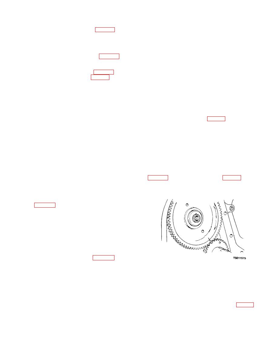
the timing marks on the camshaft and crankshaft gears
(1) Clean all parts with cleaning solvent (Fed.
Spec. P-D-680); dry thoroughly.
camshaft.
(2) Inspect the camshaft for cracks, worn or
scored cams, worn or scored bearing surfaces, chipped
or cracked keyway, and clogged oil passages. Use
compressed air to check oil passages for clogging.
Refer to table 4-1 for wear limits. Replace a damaged
camshaft.
(3) Inspect the thrust washer for scoring and
wear. Replace the thrust washer if you find any signs of
wear.
(4) Inspect the cam gear for cracked,
chipped, or broken gear teeth, damaged shaft bore, or
worn thrust surface. The cam gear and the mating gear
on the crankshaft must be replaced as a pair. Do not
attempt to replace these gears singly.
(5) Inspect the plug (34, fig. 4-21) in the
cylinder block. Replace plug if any leaking is evident
from its circumference.
Figure 4-19. Timing gears showing alinement
(6) Inspect the camshaft bearings in the
marks.
cylinder block for scoring or visible damage; replace
damaged bearings if necessary. Check the camshaft-to-
bearing clearance and, if necessary, replace bearings as
(3) Check camshaft end play with a dial
follows:
indicator. If end play is not between 0.005 (0.0125 cm)
and 0.009 (0.0225 cm) inch, remove the camshaft
CAUTION
timing gear and replace the thrust plate (18, fig. 4-3).
Do not insert the camshaft too far into the
(4) Check the clearance between the
block. If the camshaft bumps the expansion
camshaft and crankshaft gears as follows:
plug on the drive end of the engine, an oil
(a) Force the teeth of the gears apart with
leak could result.
a screwdriver. Attempt to insert a 0.002 inch (0.0050
4-19
|
|
Privacy Statement - Press Release - Copyright Information. - Contact Us |