 |
|||
|
|
|||
|
Page Title:
Figure 4-16. Checking bearing clearance with plastigage. |
|
||
| ||||||||||
|
|
 TM 5-4320-234-34
Figure 4-16. Checking bearing clearance with
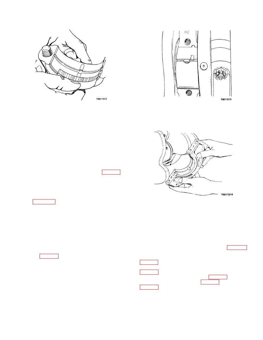
Figure 4-17. Installing upper bearing half, using
plastigage.
angular pin.
(6) Clearance must be between 0.0007
(0.0017 cm) and 0.0028 inch (0.0070 cm). If the
clearance is not within these limits, replace the bearings
and recheck the clearance.
(7) Remove and replace the bearings as
follows:
(a) Remove the bearing cap; remove the
bearing from the cap.
(b) Install a pin with an angular head into
the oil hole in the crankshaft bearing journal (fig. 4-15).
(c) Rotate the crankshaft by hand. The
pin will force the top bearing half out of its seat.
(d) Position the replacement bearing on
the crankshaft bearing journal. Rotate the crankshaft by
hand. The pin will force the bearing half into position as
shown in figure 4-17.
(e) Install the replacement bearing half
Figure 4-18. Checking bearing clearance with shim
into the cap. Install the cap.
stock.
(8) Check the remaining bearing-to-bearing
journal clearances and replace bearings as necessary.
tolerance. Remove the shim stock and reinstall the
(9) An alternate method of checking bearing
bearings caps.
clearance is as follows:
(10) After you have installed all main bearings,
(a) Oil the bearing and bearing journal
use a dial indicator to check crankshaft end play. If end
with engine oil.
play is not between 0.003 (0.0075 cm) and 0.008 inch
(b) Position a strip of 0.003-inch (0.0075
(0.0200 cm), replace the thrust plate (23, fig. 4-13)
cm) feeler gage, 1/2 inch (1.250 cm) long, on the
which controls the shaft end play.
bearing cap (fig. 4-18).
(11) Install the pistons and connecting rods
(c) Install the cap onto the block; secure
with the screws and lockwashers. Tighten the screws to
(12) Install the flywheel housing and flywheel
85 to 95 foot-pounds (11.75 to 13.13 kgm) torque.
(d) Try to turn the crankshaft by hand. If
(13) Install the gear cover (para 4-7c).
you cannot turn the crankshaft or if a very definite drag
(14) Install the oil pan (para 4-5c) and oil pump
is felt, bearing-to-bearing journal clearance is within
4-18
|
|
Privacy Statement - Press Release - Copyright Information. - Contact Us |