 |
|||
|
|
|||
|
|
|||
| ||||||||||
|
|
 mounted on the control panel which is located on the
b Removal and Disassembly.
pumping assemblies. Refer to figure 1-4 for the wiring
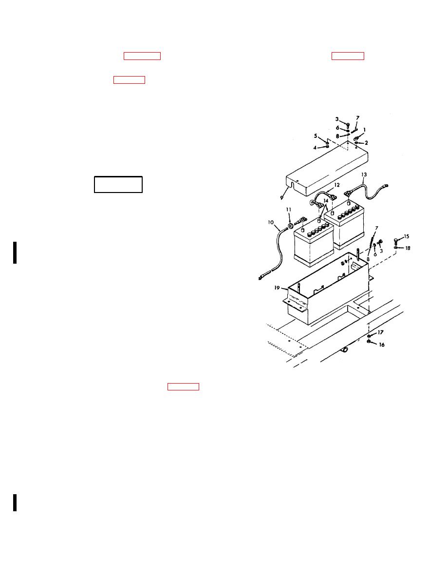
(1) Remove the wing nut (1, fig. 4-24) and flat washer
diagram showing the electrical connections between the
(2), and remove the battery box cover (9). If any of the
engine and controls. The function of the controls and
parts are damaged, remove the cap screws (3), nuts (4),
lock washers (5), and flat washers (6), and remove the
instruments is described in table 2-1
chain (7) and S-hooks (8).
g. The starter switch, mounted on the control panel,
closes the circuit to energize the starting motor. When
the push-button is released, the starting motor
deenergizes.
h. The ignition switch, mounted on the control
panel, grounds the magneto and stops the engine. This
switch is in the same circuit as the oil pressure safety
switch.
4-37. Batteries and Cables
a. Service. To charge batteries, proceed as
follows:
WARNING
Do not smoke or use an open name in
the vicinity when servicing the
batteries. Batteries generate hydrogen
gas, which is highly explosive.
(1) Remove caps and check the electrolyte
level in each cell. If any are low, fill to proper level with
distilled water or good grade drinking water (excluding
mineral water).
(2) Start engine and allow it to run for 10 to 15
minutes. Stop the engine and check the batteries with a
hydrometer.
Fully charged batteries shall have a
minimum specific gravity of 1.275 at 75 F.
CAUTION
Constant-current battery charging is
always preferred. If you must use a
constant-potential
charger,
battery
temperatures must be maintained at
less than 130 F by interrupting the
charging procedure as this temperature
is approached.
(3) If the specific gravity of the electrolyte is
1.
Wing nut
11.
Insulating grommet
less than 1.250, the batteries must be charged before
2.
Flat washer
12.
Jumper cable
use. A battery-charging receptacle (5, fig. 3-2) is
provided at the lower left rear of the engine housing.
3.
Cap screw
13.
Ground cable
Connect the charger into this receptacle. When you
4.
Nut
14.
Battery
charge the batteries, use a constant current charger.
5.
Lock washer
15.
Cap screw
Check the specific gravity of the electrolyte every 30
6.
Flat washer
16.
Nut
minutes. The batteries are fully charged when you get a
7.
Chain
17.
Lock washer
constant specific gravity reading for three 30-minute
8.
5-hook
18.
Lock washer
intervals.
9.
Battery box cover
19.
Battery box
(4) During charging, check the electrolyte level
10.
Battery cable
frequently. Add distilled water when necessary to
maintain the battery electrolyte level. Continue charging
Figure 4-24. Batteries, battery box, and cables,
after adding water to ensure proper mixing of the
exploded view.
solution.
NOTE
Military batteries and maintenance free
batteries cannot be mixed.
(5) Charge the battery a minimum of once each month
when the battery is not in service. If the battery fails to
take or maintain a charge, replace it.
Change 1
4-40
|
|
Privacy Statement - Press Release - Copyright Information. - Contact Us |
