|
| |
APPENDIX A
ASSEMBLY
If new blades are installed, they may need to be fitted to
the meter housing, refer to clearance chart in Table I.
After assembling the rotor, it should be installed in the
meter housing and the clearances determined with a
leaf feeler gage. Usually the blade edges of new blades
require dressing down to bring the blade ends within the
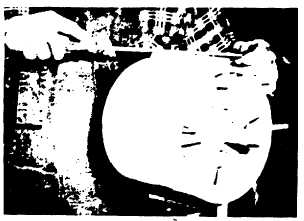
proper clearance. Figure 11 shows the proper manner
in which to accomplish this filing operation. Caution:
Use a vise with soft jaws, or otherwise properly protect
the blade held by the vise. A Vixen (babbit metal) file is
recommended for aluminum blades and a Mill coarse
file is recommended for cast iron blades.
FIG. 11. PROPER METHOD OR FILING ALUMINUM
BLADES.
Care should be exercised in replacing the Meter Cover
to insure that the lower Jack Shaft Gear engages the
Rotor Gear before pressing the cover into final position.
It is recommended that the rotor assembly be bottomed
when installing the meter cover. Insert three or four of
the cover cap screws, the shaft cone, and shaft upper
nut, and test rotor operation before installing all screws
for final tightening.
The Rotor and Blades should not touch the top, side, or
bottom of the Meter Body. Top and bottom clearances
can be adjusted by the adjusting screw. If a Meter is
clean, properly adjusted, and in good condition, the
Rotor can be turned by hand by applying slow, even
torque to the Jack Shaft Pinion. Some force is required
to turn the pinion. If Rotor drag exists, it can be
detected. Never use pliers to turn the Pinion or Shaft.
To adjust Rotor top and bottom clearance, loosen
Adjusting Locking Screw. Then, while applying torque to
Jack Shaft Pinion, turn adjusting screw until a position is
found where the rotor turns freely. The Meter tends to
act as a pump when the Rotor is turned, accordingly the
Rotor cannot be turned by hand unless all liquid is
drained from the Meter. If the Meter is not taken out of
the piping system, the inlet and outlet connections
should be freed to allow air to enter and discharge.
When the free turning position has been found, and with
the Rotor still being turned, the Adjusting Screw should
be backed off slightly until the Rotor can be felt rubbing
the Top Cover. Mark the Adjusting Screw position and
reverse the operation, turning the adjusting screw down
until the Rotor rubs the Bottom Cover, then mark the
Adjusting Screw at this position. Next set the Adjusting
Screw half way between the two marks to obtain equal
clearance between the Rotor and Top and Bottom
Covers.
If the Rotor cannot be adjusted properly, indications are
that the Rotor and Blades, etc. , have not been properly
assembled, and the complete assembly must be
removed and the cause of the difficulty located and
eliminated.
REVERSING INSTRUCTIONS
All Meters except the Double Case Type can be
reversed with regard to direction of flow. Unless
otherwise specified, a Meter is assembled at the factory
to flow left to right, when viewing the Meter from the
flanged side. If it is desired that the Meter flow from
right to left, it may be changed as follows:
a.
Remove the screws holding the counter adapter
to the Meter Cover, and lift the entire assembly
from the Meter Cover. This will expose the
gears to be reversed on S-13 and "T" meters,
where the counter adapter is incorporated in the
cover, the calibrator must be removed to
expose the gears to be reversed.
b.
See Reversing Diagram, Figure 13.
c.
Remove the cotter pins from the Intermediate
and Jack Shafts.
A9-24
|

