|
| |
APPENDIX A
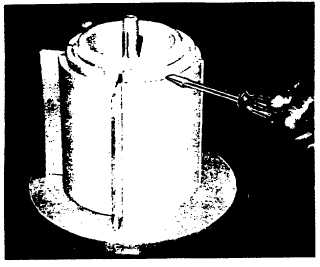
FIG. 10. REMOVING ROTOR COVER, TOP OF SCREW-
DRIVER IS PLACED IN SLOT AND PRIED
UPWARD TO PREVENT DAMAGE TO TOP EDGE
OF ROTOR.
to remove scale, etc., after which all parts should be
thoroughly washed in solvent or kerosene. The Blade
Rollers or bearings must revolve freely on their shafts
without excessive looseness. If the Blade Rollers
(bearings) are worn, they must be replaced. Blade
Roller or bearing replacement is not normally attempted
in the field but can be accomplished with proper
equipment and care.
If any burrs are apparent on the blades, they should be
removed. Sharp, clean cut edges should be maintained
on the blades. Blade blocks should be flat and clean, if
grooved they maybe turned over and used on the
opposite side, otherwise they should be replaced. If the
Rotor is equipped with rotor cover rollers and pins, these
should also be replaced if they show wear or roughness.
Reassemble in reverse order from disassembly, being
sure that al I bearing locks are properly positioned.
The jackshaft extends through a replaceable cartridge
type Packing Gland in the single case meters. Remove
Jack Shaft Pinion and draw the Shaft from the Gland. If
the Jack shaft is worn or corroded, it should be replaced,
otherwise it may be cleaned and polished with a fine
crocus cloth. Polish with a rotary motion so as not to cut
vertical grooves or scratches in the Shaft. Coat the
Shaft with light grease before inserting in the gland. If
the Packing Gland is worn, replace with a new Gland
cartridge and gasket. Check Jack Shaft Bushing and
replace if worn.
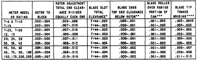
TABLE 1 - CLEARANCE GUIDE
THIS CLEARANCE GUIDE LISTS THE RECOMMENDED MINIMUM AND MAXIMUM FITTING CLEARANCES FOR NEW AND REPAIRED
METERS. CLEARANCES MAY EXCEED THE MAXIMUM SHOWN PROVIDED THE METER PROVES WITHIN ACCEPTABLE ACCURACY.
THE ABOVE CLEARANCES APPLY ONLY TO METERS OPERATING AT
STANDARD OPERATING TEMPERATURES OF 20
TO 150°F. AND
VISCOSITIES LESS THAN 5,000 SSU. FOR HIGHER TEMPERATURES
AND VISCOSITIES CONSULT FACTORY.
*BLADES SHOULD MOVE FREELY IN ROTOR SLOTS AND THE
AVERAGE CLEARANCE IN EACH SLOT SHOULD NOT EXCEED THE
LISTED CLEARANCES. NOR SHOULD ANY SINGLE POINT BE MORE
THAN 50% ABOVE THE MAXIMUM LISTED.
**THE BLADE SHOULD BE SHORTER THAN THE ROTOR BY THE
AMOUNT SPECIFIED TO ALLOW FOR DIFFERENCE IN COEFFICIENT
OF EXPANSION BETWEEN THE ALUMINUM BLADES AND IRON
ROTOR. (LOWER EDGE OF BLADE SHOULD NOT PROJECT
BELOW BOTTOM SURFACE OF ROTOR.)
***WITH THE BLADE IN THE MEASURING CHAMBER. THIS
TOTAL CLEARANCE SHOULD BE MAINTAINED BETWEEN THE
RADIUS OF THE CAM AND ONE ROLLER ONLY.
****WITH THE BLADE HELD TOWARD (AWAY ON T-6 AND T-10)
THE HOUSING, THESE CLEARANCES SHOULD BE MAINTAINED
BETWEEN THE MEASURING CHAMBER AND THE FULL LENGTH
OF THE EDGE OF THE BLADE.
A9-23
|