|
| |
APPENDIX A
Clearances should be checked with a leaf type feeler
gage. Any average of clearances that are outside of the
tolerance should be noted with a view toward replacing
the worn parts. It is well to call attention to the fact that
although certain parts may be at or over the borderline
of the maximum allowable tolerance, consideration
should be given to the condition of the part and the
accuracies being obtained in calibrating the meter. By
this it is meant that certain major parts such as the rotor
and blades need not be replaced if no difficulty is
experienced in proving the meter and records show that
there is no appreciable change in accuracy from one
meter proving to another.
With the rotor assembly still in the meter housing, blade
roller and/or cam clearances can be checked by moving
the blades back and forth against the cam. Each blade
should be checked in two positions, one position at right
angles to the first position. This determination can
usually be made visually.
It is recommended that a support be used to
disassemble the rotor. A simple and inexpensive work
plate can be fabricated from pipe and steel plate.
Before attempting further disassembling, turn the rotor
and shaft assembly upside down on the support plate.
On the T-15 Meter, drive out the pin that holds the shaft
key and remove the key. The S13 sump plate is
fastened to the shaft with Allen head set screws, 90
degrees apart, with two set screws at each location. Be
sure to remove the first one completely, 'then loosen the
other screws that hold the rotor cover to the rotor and
carefully pry off the Rotor Cover. This should be done
in such a manner so as not to damage the edge of the
rotor. ( See Figure 10.) Remove the lower bearing and
bearing cover from the shaft. Mark position of blades
using a punch or file with relation to rotor slots. This will
permit replacement in their respective slots and in the
same positions.
Next, carefully lift out the lower blade and then withdraw
the shaft. The upper blade can then be removed. Turn
the Rotor over and remove the Rotor Gear Plate,
making the Upper Radial Bearing and the Thrust
Bearing accessible. Clean all parts thoroughly. Fine
emery cloth may be used to remove scale, etc., after
A9-22
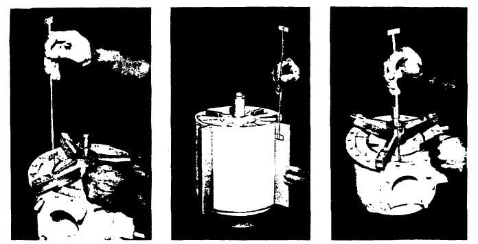
FIG. 7.
USING FEELER GAUGE TO
CHECK BLADE TO HOU-
SING CLEARANCES.
FIG. 8.
CHECKING BLADE SLOT
CLEARNCE WITH FEELER
GAUGE. CLEARANCES
MAY BE CHECKED WITH
BLADES POSITIONED IN-
SIDE OF OR OUTSIDE OF
ROTOR,
BUT
ROTOR
COVER MUST BE ON.
FIG. 9.
CHECKING CLEARANCES
BETWEEN
ROTOR
AND
BLOCK.
|