|
| |
TIM10-4930-246-13&P
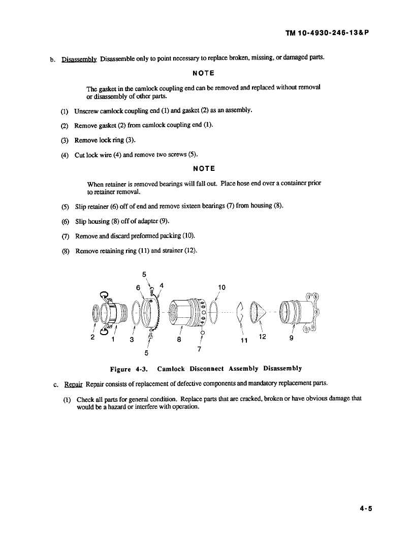
b. DisassemblyDisassembleonlytopointnecessarytoreplacebroken,missing,ordamagedparts.
NOTE
The gasket in the camlock coupling end can be removed and replaced without removal
or disassembly of other parts.
(1) Unscrew camlock coupling end (1) and gasket (2) asan assembly.
(2)Remove gasket (2) from camlock coupling end (1).
(3) Remove lock ring (3).
(4) Cut lock wire (4) and remove two screws (5).
NOTE
When retainer is removed bearings will fall out. Place hose end over a container prior
to retainer removal.
(5)
Slip retainer (6) off of end and remove sixteen bearings (7) from housing (8).
(6) Slip housing (8) off of adapter(9).
(7)
Remove and discard preformed packing (10).
(8)
Remove retaining ring (11) and strainer (12).
5
6
4
10
1
3
12
9
2
8
11
5
7
Figure
4-3.
Camlock
Disconnect
Assembly
Disassembly
c.
RM&
Repair consists of replacement of defective components and mandatory replacement parts.
(1)
Check all parts for general condition. Replace parts that are cracked, broken or have obvious damage that
would be a hazard or interfere with operation.
4-5
|