|
| |
TM 10-4320-347-13&P
d.
Assembly.
(1) Place one of the wires (8) into each of the cutouts in the receptacle (5) and install two wire assemblies
(8), two lock washers (7), and two bolts (6) into receptacle (5).
(2) Install cover (4), cap retaining cable (3), six flat washers (2), and six screws (1).
(3) Squeeze RTV sealant into two cable openings where two wire assemblies (8) enter the receptacle. Be
sure RTV sealant will provide a watertight seal around wire assemblies.
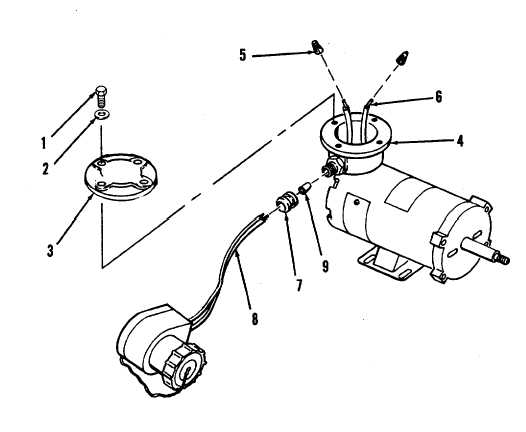
Figure 4-4. Slave Cable Replacement.
c.
Installation . (Refer to Figure 4-4).
(1) Place strain relief nut (7) and rubber seal (9) on slave cable wires (8).
(2) Install slave cable wires (8) into motor junction box (4). Pull about 6" of slave cable wires through
strain relief nut (7).
(3) Snug rubber seal (9) down to strain relief. Tighten strain relief nut (7).
4-9
|