 |
|||
|
|
|||
|
|
|||
| ||||||||||
|
|
 TM 10-4320-202-15
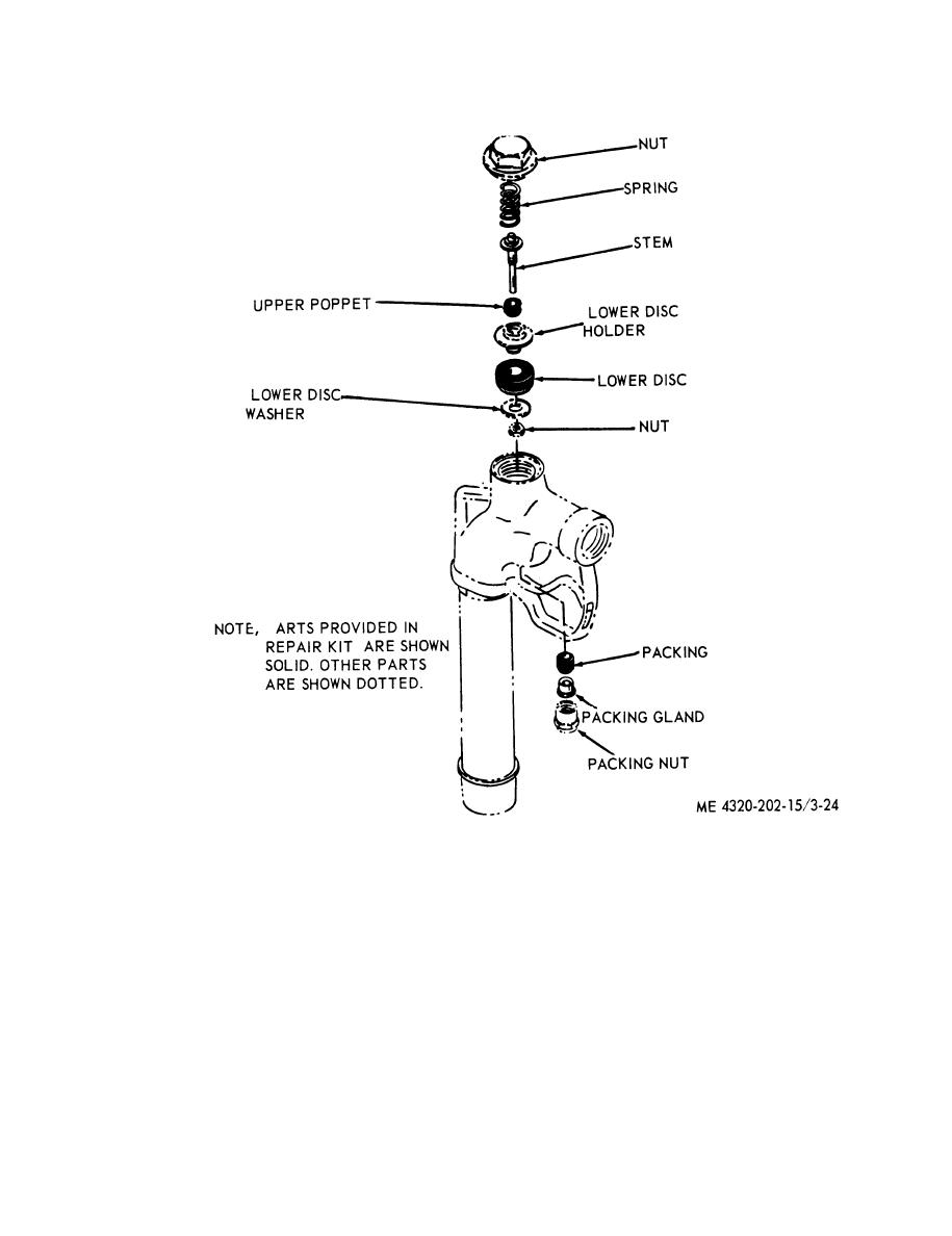
Figure 3-24. Nozzle disassembly and reassembly.
Section XII. PUMP ASSEMBLY
end of the engine crankshaft. Impeller-to-body
3-46. General
clearance is regulated by shims between the
The pump body is bolted to the coupling head
c o u p l i n g head and pump body. A seal is
which is in turn bolted to the power takeoff
installed between the engine shaft and the
end of the engine. The pump impeller is thread-
coupling head to prevent fluid from leaking
ed and screws directly to the power takeoff
around the rotating shaft.
3-29
|
|
Privacy Statement - Press Release - Copyright Information. - Contact Us |