|
| |
TM 10-3835-231-13
2-6. OPERATING PROCEDURES. - continued
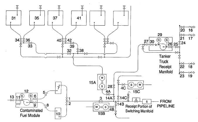
Figure 2-25. Fuel Transfer Schematic
(d) Empty the contaminated fuel tanks as follows:
1 Open valves (5) and (6) to pump out tank (7) or valves (8) and (9) to pump out tank (10).
2 Connect the 3-inch coupling to the tanker-truck.
3 Open valve (11).
4 Start the pump (12) and pull suction from the tank while opening valve (13).
5 When pump out is complete, close valve (13) and immediately shut down pump (12).
6 Close valves (5), (6), (8), and (9) as appropriate.
(3) Receive fuel from the pipeline as follows:
(a) Reset meter (15A), (15B), or (15C) as appropriate to zero or record the reading.
(b) Open valves in the hoseline route to appropriate tank.
1 To (31). Open 4A, (32), (33), and (34).
2 To (35). Open 4A, (32), (33), and (36).
3 To (37). Open 4A, (38), (39), and (40).
2-60
|