 |
|||
|
|
|||
|
Page Title:
Section X. MAINTENANCE OF NON-ELECTRICAL GAGES |
|
||
| ||||||||||
|
|
 or binding dial pointers, damaged terminals,
evidence of entry of moisture, and other damage.
Replace damaged gages and meters.
(3) Check all switches for cracked cases,
difficult operation, lack of positive switch action,
and other damage. When you check the switches
for continuity, use a multimeter or test lamp.
Replace defective switches.
( 4 ) Inspect the magneto stop switch for
cracks, loose or damaged terminals, and other
damage. Continuity should not exist when the
switch is in the run position; continuity should exist
when the switch is in the stop position. Replace a
damaged or inoperative magneto switch.
(5) Inspect the hoses for cuts, abrasions,
l e a k s , damaged threads, and other damage.
Replace damaged hoses.
(6) Check the operation of the oil pressure
safety switch by checking continuity across the
terminals while you apply air pressure to the
pressure port. Start with the switch in the reset
position (with the spring clip inserted under the
recess in the housing). No continuity must exist at
this time. Slowly apply air pressure. When ap-
proximately 1 psi pressure is applied, the spring
clip must disengage from the housing, with no
continuity being maintained through the switch.
Increase pressure to maximum 5 psi, then reduce
pressure. W h e n y o u l o w e r p r e s s u r e t o a p -
proximately 1 psi, continuity must be established
and must remain when the pressure is further
reduced to zero. Replace the switch if it fails to
perform as indicated.
b. Cleaning and Inspection.
( 7 ) Inspect all other p a r t s f o r c r a c k s ,
WARNING
distortion, damaged threads, and other damage;
Clean all parts in a well-ventilated area.
replace damaged parts.
-
.
Avoid inhalation of solvent fumes and
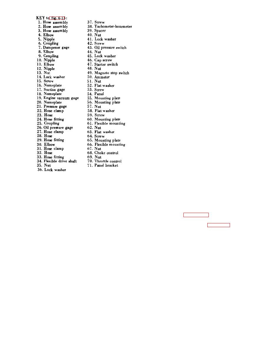
c. Reassembly and Installation.
prolonged exposure of the skin to
(1) Reassemble and install the controls, in-
cleaning solvent. Wash exposed skin
d i c a t o r s , and gages in the opposite order of
thoroughly.
removal; refer to figure 4-13.
(1) Clean all parts by wiping them with a
(2) Connect the electrical leads to the properly
cloth dampened lightly with cleaning solvent (fed.
tagged components. Refer to figure 1-3, wiring
spec. P-D-680). You must be careful to prevent the
diagram.
solvent from entering the interior of the com-
(3) After installation, start the engine and
ponents.
check that you have proper operation of switches
(2) Inspect all meters and gages for cracked
and gages. Check thoroughly for leaks.
dial glass, defaced or illegible dial marking, sticking
Section X. MAINTENANCE OF NON-ELECTRICAL GAGES
each gage to prevent momentary pressure surges
4-29. Description
from damaging the re!ated gage.
a. Three large gages on the engine control panel
k e e p you informed of the pump suction and
control panel is driven by a flexible drive shaft
discharge pressures, and the engine vacuum. They
which connects to a drive adapter on the governor.
are connected to their related system by hoses and
fittings. Each system incorporates a dampener at
|
|
Privacy Statement - Press Release - Copyright Information. - Contact Us |
