 |
|||
|
|
|||
|
Page Title:
Section V - REMOVAL AND INSTALLATION OF MAJOR COMPONENTS |
|
||
| ||||||||||
|
|
 Section V - REMOVAL AND INSTALLATION OF MAJOR COMPONENTS
3-17. GENERAL - This section provides information for removing the pump and engine from, and installing them on,
the trailer frame.
3-18. ENGINE AND PUMP
A. GENERAL - The pump is directly coupled to the engine, and the pump impeller is driven by a splined shaft and
coupling, the latter of which is bolted to the engine flywheel. When removing the pump or engine, the pump and engine
are removed from the trailer frame as a unit, and then separated as required.
B. REMOVAL
1. Remove the lifting bail (para. 3-16. A).
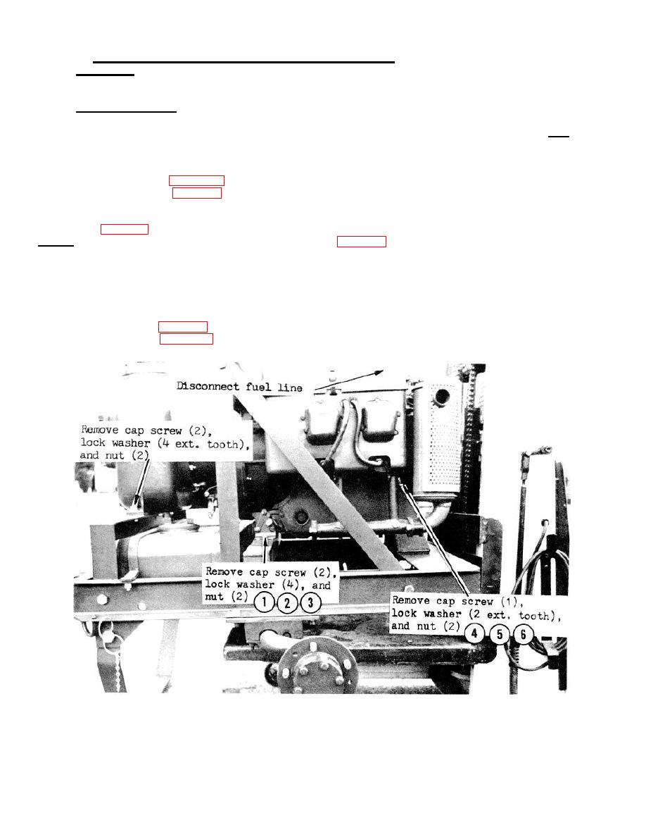
2. Disconnect the fuel line (Fig. 3-13).
3. Connect a suitable lifting device in threaded hole on top intermediate housing and block.
4. Disconnect battery cables from the engine.
5. Refer to Fig. 3-13, remove the mounting hardware, and lift the engine and pump assembly from the trailer.
NOTE: To separate the engine and pumping assembly, refer to para. 4-2.
C. INSTALLATION
1.
Position the engine and pump assembly on the trailer frame, and install the mounting hardware as shown in Fig. 3-
13.
2.
Remove the lifting device from the pump and engine assembly.
3.
Connect battery cables to the engine.
4.
Connect the fuel line (Fig. 3-13).
5.
Install the lifting bail (para. 3-16. A).
FIGURE 3-13. REMOVAL OF MAJOR COMPONENTS
24
|
|
Privacy Statement - Press Release - Copyright Information. - Contact Us |
